
Loading tool...
The Inverting Op Amp Resistor Calculator is a practical tool for analyzing operational amplifier inverting circuits. By entering parameters such as the desired gain, output voltage (Vout), R1 resistance, and the input voltages V1, V2, Vp, and Vn, the calculator automatically determines the required resistor values (R2, R3, and R4). Simply input the values and click “Calculate” to quickly design and verify inverting op amp configurations.
Enter your parameters below to calculate results.
The OP AMP Resistor Calculator is a professional design tool used to determine the correct resistor values (R2, R3, and R4) for an inverting operational amplifier circuit.
To use this tool effectively, you typically need to define the following input parameters:
This tool simplifies the design process by automatically computing the feedback and stabilization resistors needed to achieve specific gain and bandwidth targets.
The Inverting Amplifier is one of the most fundamental and widely used operational amplifier circuits. It is simple to construct, requiring only a few discrete components.
Key Characteristic: As the name suggests, the output voltage signal is inverted relative to the input voltage signal. This means there is a phase shift between input and output.
The voltage gain () of an inverting amplifier is determined by the ratio of the feedback resistor () to the input resistor ():
Below is a visual comparison of the two most common amplifier configurations.
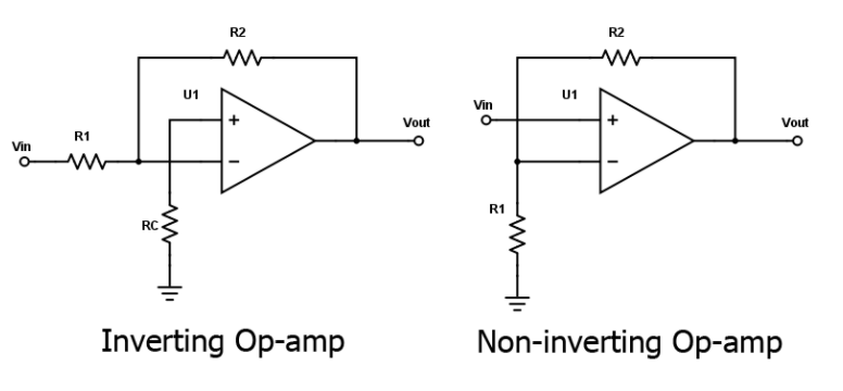
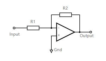
How it works: In this configuration, the Non-Inverting Input (+) is connected directly to the ground. The input signal is applied to the Inverting Input (-) through a resistor ().
The Concept of "Virtual Ground":
How it works: In a Non-Inverting Amplifier, the input signal is applied directly to the Non-Inverting Input (+). The feedback comes from the output to the Inverting Input (-).
Key Differences:
Here are other essential calculators often used alongside Op-Amp design: