
The MAX5391/MAX5393 dual 256-tap, volatile, low-voltage linear taper digital potentiometers offer three end-to-end resistance values of 10kΩ, 50kΩ, and 100kΩ. Operating from a single +1.7V to +5.5V power supply, these devices provide a low 35ppm/°C end-to-end temperature coefficient. The devices feature an SPI interface.The small package size, low supply voltage, low supply current, and automotive temperature range of the MAX5391/MAX5393 make the devices uniquely suitable for the portable consumer market and battery backup industrial applications.The MAX5391/MAX5393 include two digital potentiometers in a voltage-divider configuration. The MAX5391/MAX5393 are specified over the -40°C to +125°C automotive temperature range and are available in a 16-pin, 3mm x 3mm TQFN and a 14-pin TSSOP package, respectively.
YG GROUP (YUGUANG INTERNATIONAL(HK)CO.,LTD) supports reliable sourcing through quality controls and compliance documentation. Please confirm product requirements, applicable certifications and supporting documents before ordering.
MAX5393MAUD+ is an authentic electronic component manufactured by Analog Devices, categorized under Digital Potentiometer ICs. It is supplied in the standard manufacturer-specified package footprint, providing industry-standard mechanical dimensions and terminal configurations for board-level assembly. Full pinout configurations, physical footprint drawings, and rated operating tolerances are documented in the official MAX5393MAUD+ datasheet above.
Electronic component spot-market pricing for MAX5393MAUD+ fluctuates based on real-time global availability, production date codes, minimum order quantities (MOQ), and packaging formats (e.g., Reel, Tube, Tray). Using an RFQ ensures you receive accurate, real-time volume pricing tied to verified, traceable inventory rather than stale catalog estimates.
Lead times for MAX5393MAUD+ depend on whether stock is dispatched from our central hub or regional franchise partners. Ready-to-ship inventory typically leaves the warehouse within 1–3 business days following quality inspection, while factory-direct or back-ordered allocations are confirmed with an estimated ship date upon RFQ reply.
Loading articles…

Loading articles…

Calculate AD9255 jitter limits from input frequency. Distinguish dB from dBFS and review differential clock coupling, DCS and ground-return paths.
Read more →
Coordinate TLC5941-Q1 grayscale duty and dot-correction current. Check startup order, the first GS transfer after DC, and clock and thermal margins.
Read more →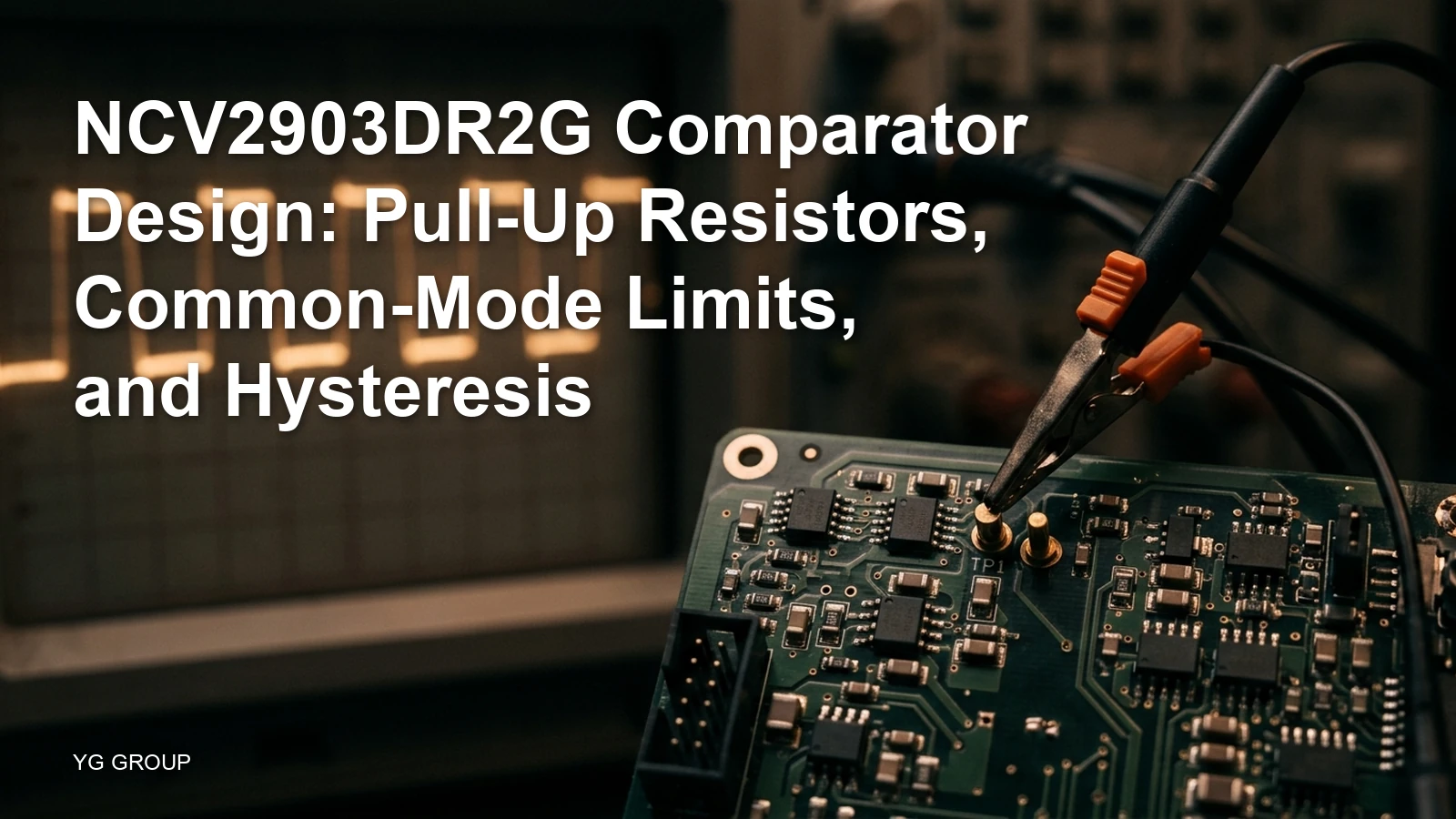
Design NCV2903 thresholds with common-mode limits, receiver logic requirements and calculated hysteresis. Separate pull-up rise time from propagation delay.
Read more →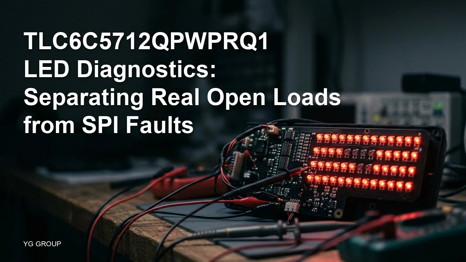
Check TLC6C5712-Q1 power, 16-bit SPI, channel flags and PWM diagnostic windows. Use separate status and POR resets to investigate an LED fault.
Read more →Loading related products…
| Picture | Part Number | Manufacturer | PDF / RoHS | Stock | Action |
|---|---|---|---|---|---|
 | Analog Devices | 3,570 | |||
 | Analog Devices | 3,950 | |||
 | Analog Devices | -- | 5,280 | ||
| Analog Devices | 1,110 | |||
| Analog Devices | 5,160 | |||
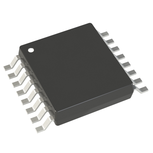 | Analog Devices | 5,530 | |||
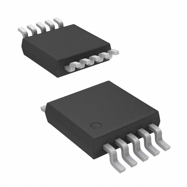 | Analog Devices | 3,280 | |||
| Analog Devices | 3,810 | |||
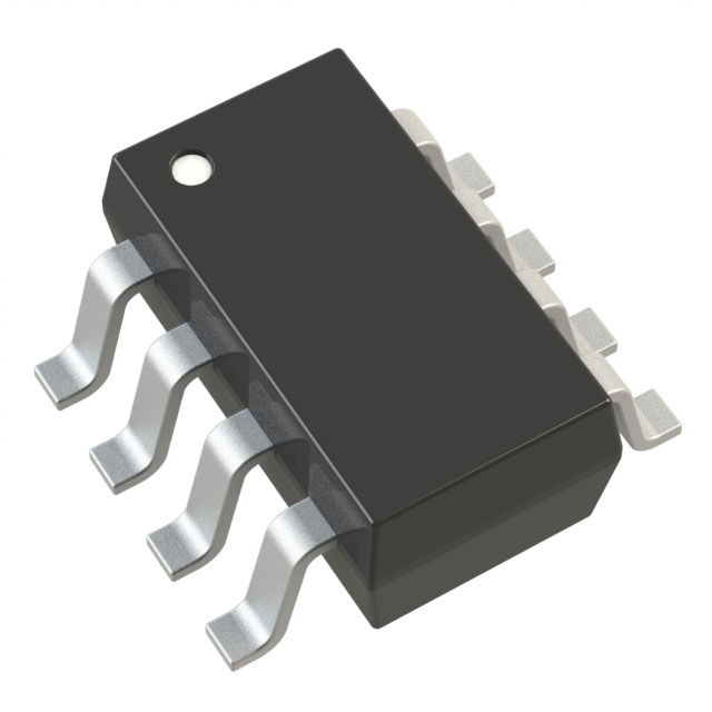 | Analog Devices | 1,090 | |||
| Analog Devices | 4,060 |
