
Georgia Huang




| Picture | Part Number | Manufacturer | Stock | Action |
|---|---|---|---|---|
 | AD8628ARTZ-REEL7 | Analog Devices | 3,000 | |
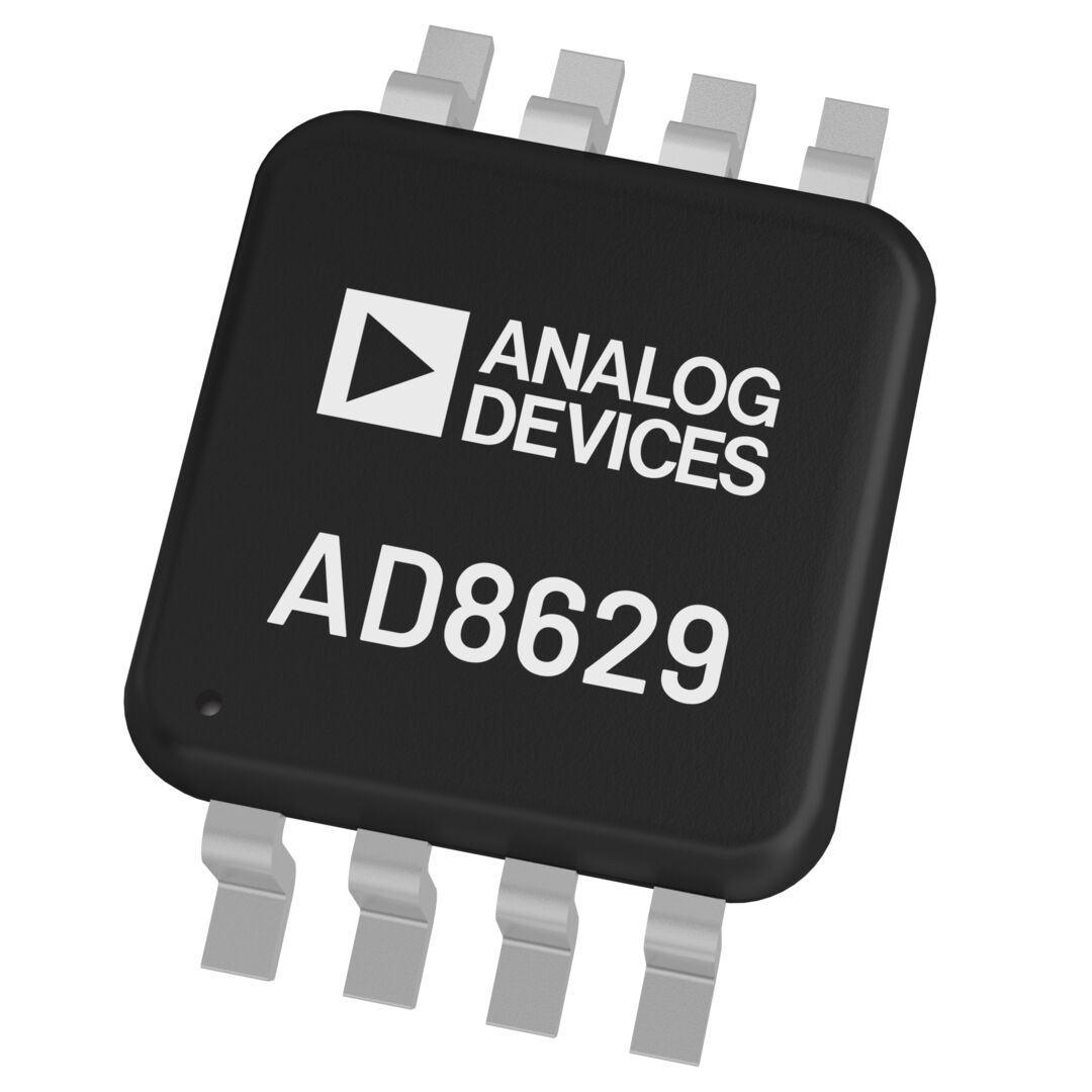 | AD8629ARMZ-REEL | Analog Devices | 2,280 | |
 | AD8630ARUZ-REEL | Analog Devices | 6,910 |
At 5 V supply, 2.5 V common mode and 25 C, offset is 1 microvolt typical and 5 microvolts maximum. The maximum is 10 microvolts over -40 C to +125 C. Use the limit that covers the product's actual temperature range. At gain 100, the 5 microvolt input limit corresponds to 0.5 mV output offset while operating linearly.
It can reduce the amplifier-drift contribution when that contribution drives calibration effort. Sensor nonlinearity, resistor mismatch and reference error still need treatment. Evaluate the same channel, gain, bandwidth and temperature span before and after the change, then determine which factory or field adjustment can be reduced.
Input bias current creates an error across source impedance, and output headroom depends on load. At the 5 V, 25 C table conditions, AD8628 bias current is 30 pA typical and 100 pA maximum. Guaranteed high output is at least 4.99 V with 100 kOhm to ground, versus 4.95 V with 10 kOhm. Budget the real sensor and converter connections.
Category: Manufacturer Insights
By Georgia Huang
AD8628ARTZ-REEL7 is a single zero-drift operational amplifier from Analog Devices in a five-lead SOT-23 package. It is a useful candidate when low-frequency offset and temperature drift consume the error budget of a sensor channel. The buying decision still depends on noise bandwidth, source impedance and output loading. Zero-drift technology reduces particular amplifier errors; it does not remove sensor errors or automatically eliminate calibration.
AD8629ARMZ-REEL is a dual amplifier in eight-lead MSOP, and AD8630ARUZ-REEL is a quad in fourteen-lead TSSOP. They can consolidate channels in a redesign. AD8630 also has a higher 25 C maximum input bias current, 300 pA versus 100 pA for AD8628/AD8629. Review source impedance, routing and total supply demand with the channel count.
The Rev. M ordering guide specifies 3,000 devices per reel in five-lead SOT-23. This is a packing quantity, separate from a supplier's MOQ. State whether the requirement is a full reel or evaluation quantity, and confirm the offered packing, lot records and delivery basis. Automotive requirements need the appropriate W-prefixed order code and its supporting records.
A precision amplifier purchase begins with the channel's error budget. Identify the smallest useful sensor signal, gain before conversion, temperature span and measurement bandwidth. Those inputs show whether offset, drift or noise limits the channel, and whether paying for zero-drift technology addresses that limit.
AD8628 is the single-amplifier member of the AD8628/AD8629/AD8630 family. Its datasheet describes combined auto-zeroing and chopping, rail-to-rail input/output operation and a specified single-supply range of 2.7 V to 5 V. The ordering guide identifies AD8628ARTZ-REEL7 as a five-lead SOT-23, with 3,000 devices per reel. That pack quantity is useful for production planning; the offered MOQ still belongs in the quotation. Analog Devices datasheet, Rev. M, pages 1, 14 and 20.
Low drift matters most when amplifier drift is a meaningful fraction of the channel's allowed error. A channel dominated by sensor nonlinearity, resistor mismatch or reference instability may obtain less practical benefit from upgrading the amplifier alone. The useful purchase is precision that changes the channel's limiting error.
At a 5 V supply, 2.5 V input common-mode voltage and 25 C, the datasheet specifies 5 microvolts maximum input offset; the maximum becomes 10 microvolts across -40 C to +125 C. With a gain of 100, a 5 microvolt input offset contributes 0.5 millivolt at the output while the amplifier operates linearly. This is illustrative arithmetic using the stated offset limit, not a measured board result. It makes the procurement question concrete: which limit does the channel need, and under which temperature conditions? Electrical specifications, page 3.
Offset, temperature drift and noise describe different behaviors. Offset creates a baseline error. Drift changes that baseline with temperature. Noise produces variation over the measurement bandwidth. A calibration at one temperature can address a repeatable baseline, but it does not demonstrate the channel's behavior over temperature or remove random noise.
The datasheet distinguishes 0.5 microvolt peak-to-peak typical noise over 0.1 Hz to 10 Hz from 22 nV/sqrt(Hz) typical noise density at 1 kHz. The units and bandwidths answer different questions. An abbreviated "low-noise" description cannot establish either result for a complete sensor channel. The final gain, filter and measurement method need to accompany an electrical acceptance requirement. Datasheet electrical table and noise plots, pages 3 and 11-15.
Table 1. Precision specifications to carry into the evaluation
| Parameter | Datasheet value | Evaluation consequence |
|---|---|---|
| Input offset | 1 microvolt typical, 5 microvolts maximum at 25 C; 10 microvolts maximum across -40 C to +125 C | State gain and the temperature range for the channel limit |
| Offset drift | 0.002 microvolt/C typical; 0.02 microvolt/C maximum over -40 C to +125 C | Keep the typical headline separate from the design limit |
| Low-frequency voltage noise | 0.5 microvolt peak-to-peak typical, 0.1 Hz to 10 Hz | Specify measurement bandwidth and method |
| Voltage noise density | 22 nV/sqrt(Hz) typical at 1 kHz | Assess the actual filter bandwidth, not this number alone |
| AD8628 input bias current | 30 pA typical, 100 pA maximum at 25 C | Include source impedance in the error budget |
Source: Analog Devices AD8628/AD8629/AD8630 datasheet, Rev. M, page 3; VS = 5 V, VCM = 2.5 V and TA = 25 C unless the row states a wider temperature range. Typical values are not guaranteed limits. Use the relevant temperature and loading conditions for the channel's acceptance limits.

Figure 1. AD8628ARTZ-REEL7 addresses amplifier offset, drift and noise, while the sensor, reference and circuit still contribute their own errors. Values use the Rev. M page 3 conditions; drift covers -40 C to +125 C. This conceptual map assigns no measured percentage shares.
For another amplifier-selection task, OPA1612AIDR audio noise and noise gain examines bandwidth-dependent noise, while LM358 versus LM358B input limits focuses on a conventional amplifier upgrade. Use those circuit requirements alongside the low-frequency error budget here when deciding which amplifier architecture to evaluate.
For a buyer, the table turns a broad precision op amp enquiry into an actionable evaluation. Ask engineering to identify the limiting error and its acceptance conditions. Preserve the distinction between a maximum specification, a typical curve and a measurement from the project board when comparing offers.
The economic case for AD8628ARTZ-REEL7 can include calibration work, but that case needs a demonstrated mechanism. If amplifier drift causes a repeated adjustment across temperature, reducing it may reduce that particular burden. If calibration is chiefly compensating the sensor or reference, the amplifier change does not answer the same problem.
Separate factory calibration from field behavior. A factory trim removes an error measured under specified conditions. Field drift, startup settling and noise determine whether the product continues to meet its limit after that trim. The useful trial compares the channel before and after the amplifier change using the same sensor, gain, bandwidth and temperature conditions.
Output loading deserves the same attention. At the page 3 conditions, the guaranteed high output is at least 4.99 V with a 100 kOhm load to ground, but at least 4.95 V with 10 kOhm. "Rail-to-rail" therefore still leaves a load-dependent headroom requirement. Record the actual signal excursion and converter load, and include settling under that load in the channel evaluation. Output characteristics, page 3.
Table 2. Two genuine family comparisons
| Exact model | Relationship to AD8628ARTZ-REEL7 | Selection boundary |
|---|---|---|
| AD8629ARMZ-REEL | Dual zero-drift member, eight-lead MSOP | Useful for two related channels; different package, pinout and total supply demand |
| AD8630ARUZ-REEL | Quad zero-drift member, fourteen-lead TSSOP | Useful when four channels share a board; channel routing and package redesign required |
Source: Shared AD8628/AD8629/AD8630 datasheet, pages 1 and 19-21; exact ordering identities also appear in AD8629 Part Models and AD8630 Part Models. These are channel-count alternatives, not interchangeable five-pin devices.

Figure 2. AD8628ARTZ-REEL7, AD8629ARMZ-REEL and AD8630ARUZ-REEL provide one, two and four channels in different packages. Channel consolidation changes routing, pinout and total supply demand; these are design comparisons, not five-pin drop-in replacements. Source: shared datasheet, pages 1 and 19-21.
For AD8628ARTZ-REEL7 alternatives, start with the number of channels the board actually needs. The dual or quad options can consolidate channels, but electrical details still differ. At the page 3 conditions, AD8628/AD8629 have 100 pA maximum input bias current, versus 300 pA for AD8630. High source impedance makes that difference worth budgeting. Shared placement, routing and total supply demand also need review before approving a different order code.
The ordering guide separately identifies W-prefixed automotive models. For an automotive BOM, select the exact qualified model and obtain its supporting records. The non-W AD8628ARTZ-REEL7 order code does not inherit that qualification from a family-level application example. Datasheet ordering/automotive notes, page 21.
Select AD8628ARTZ-REEL7 when the channel needs a single zero-drift amplifier and its offset, drift and noise behavior fit the actual measurement conditions. Compare the two related multi-channel models when consolidation is part of a new board design. Obtain a current commercial quotation only after those differences are clear.
The strongest purchasing case is a measured reduction in the channel's limiting error, with calibration effort evaluated separately. That gives the procurement manager a defensible reason for the chosen amplifier without promising zero error, automatic cost savings or unnecessary specification headroom.
To price a meaningful evaluation, enquire about AD8628ARTZ-REEL7 with YG GROUP. Include evaluation or production quantity, need-by date, the approved five-lead SOT-23 and full- or partial-reel requirements. Identify any dual or quad redesign separately. Ask which lot records and checks are available; for precision measurements, agree on gain, bandwidth, loading and temperature conditions so the requested report answers the sensor channel's actual requirement.