Veca Huang




Its typical 1 kHz current-noise density is 0.4 pA/sqrt(Hz) under TI's electrical-table conditions. Through 100 kohm that produces 40 nV/sqrt(Hz), compared with 3 nV/sqrt(Hz) typical voltage noise. Include resistor thermal noise and the real source impedance versus frequency, then integrate over the channel bandwidth. The article's 300 K scenario excludes feedback, sensor and low-frequency noise.
TI specifies a 10 nA maximum input-bias-current magnitude at 25 C and over -40 to 85 C under the stated +/-5 V to +/-15 V supply and common-mode conditions. Multiplying it by an unmatched 100 kohm gives an illustrative 1 mV contribution. Offset, drift, feedback-input impedances and calibration add other terms. Use this as a budget term rather than the total error of every circuit.
OPA2227 is unity-gain stable; OPA2228 is optimized for gains of at least five. Evaluate the complete noise gain, feedback network and capacitive load, including any required compensation, before using OPA2228 in a low-gain channel. A faster family member can introduce a stability task even if its package appears convenient.
Category: Component Selection & Alternatives
By Veca Huang
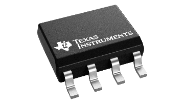
OPA2227U/2K5 is a Texas Instruments dual precision amplifier supplied in SOIC-8 on a 2,500-device reel. Choose its bipolar input around the source's noise and DC-error budget. For a high-impedance sensor, a FET-input comparison can change that choice. A faster OPA2228 sibling introduces a separate gain-stability task, so the best quotation is the one matched to the channel and the engineering work it requires.
A precision amplifier quotation often arrives with a compelling voltage-noise figure. The purchasing decision still needs the signal source. A low-resistance source and a high-impedance sensor can produce very different results with the same amplifier, even before the feedback network and analog-to-digital converter are considered.
OPA2132UA is a FET-input dual-amplifier comparison. Its different input-current behavior is relevant when source impedance makes bipolar current noise or bias-current error expensive. Compare voltage noise, input-current terms, supply/headroom, bandwidth and settling in the actual channel. OPA2277UA supplies another bipolar precision comparison; neither candidate gains board compatibility from its family name or SOIC label.
Include the complete U-grade code, quantity, delivery target and SOIC-8 carrier requirements. /2K5 identifies a 2,500-device factory reel, not a different noise architecture or a supplier MOQ. Keep the channel's source impedance, supply, gain and bandwidth available for alternative evaluation. Request smaller evaluation quantities separately and confirm their packing and commercial terms in the offer.
TI's OPAx227/228 Rev C datasheet, page 7, specifies typical voltage-noise density of 3 nV/sqrt(Hz) and typical current-noise density of 0.4 pA/sqrt(Hz), both at 1 kHz under the table's stated conditions. These are different quantities. Current noise develops a voltage across the source impedance; the two terms should not be compared by their printed numerical values alone.
OPA2227U/2K5 is a strong candidate when the complete input-noise budget supports it, not whenever a buyer finds the lowest voltage-noise number. That budget gives engineering a defensible acceptance target and purchasing a reason for choosing this part over a superficially cheaper alternative.
For a resistive source and a unity-gain buffer, a simplified input-referred noise model combines amplifier voltage noise, current noise through the resistance and the resistor's thermal noise. TI explains this model in section 7.3.6. In plain notation, the squared density is e_n squared + (i_n x R) squared + 4kTR.
The calculation below uses a 300 K resistor and the typical 1 kHz amplifier densities above. It is an illustrative calculation, not a sensor measurement, and excludes the feedback network, low-frequency effects and sensor-generated noise.
Table 1. Illustrative source-resistance noise terms at 1 kHz
| Assumed resistance | Current-noise voltage term | Resistor thermal-noise density | Approximate combined density |
|---|---|---|---|
| 1 kohm | 0.4 nV/sqrt(Hz) | 4.1 nV/sqrt(Hz) | 5.1 nV/sqrt(Hz) |
| 10 kohm | 4 nV/sqrt(Hz) | 12.9 nV/sqrt(Hz) | 13.8 nV/sqrt(Hz) |
| 100 kohm | 40 nV/sqrt(Hz) | 40.7 nV/sqrt(Hz) | 57.1 nV/sqrt(Hz) |
Source: TI Rev. C, pp. 7, 20-21; calculated by YG GROUP using k = 1.380649 x 10^-23 J/K. Rounded values are scenario results, not guaranteed device specifications.
The useful finding is the changing contribution, not a universal resistance threshold. At higher resistance, current noise becomes expensive in voltage terms. Meanwhile the resistor itself contributes noise. Paying for lower amplifier voltage noise may have little value if another term dominates the channel.
A real sensor can have impedance that varies with frequency. Substitute that behavior into the model rather than using a resistance measured at one convenient point. Integrate over the actual noise bandwidth and include the filter's transfer function. A single spectral-density figure does not give total RMS noise across the measurement band.

Figure 1. Simplified input-referred density uses 300 K, typical 1 kHz values of 3 nV/sqrt(Hz) and 0.4 pA/sqrt(Hz), and a resistive source. Combined results are 5.1, 13.8 and 57.1 nV/sqrt(Hz) at 1, 10 and 100 kohms. Calculated scenarios exclude feedback, sensor and low-frequency noise.
Input bias current introduces a DC error through source resistance. The same datasheet gives a maximum bias-current magnitude of 10 nA at 25 C and over -40 to 85 C, under its specified supply and common-mode conditions. The table's supply range is +/-5 V to +/-15 V. As an illustrative upper-bound product, 10 nA through an unmatched 100-kohm source resistance is 1 mV. That is a bias-current contribution before offset voltage, drift and system calibration are added.
The calculation should not be mistaken for the error of every circuit. Its purpose is to make the source resistance visible in the specification. Both amplifier inputs and the feedback network matter, and compensated input-bias behavior can make textbook cancellation-resistor choices unhelpful. TI specifically discusses that issue in section 7.3.5.
Separate AC noise from DC accuracy in the selection request. State acceptable input-referred noise over a defined bandwidth, maximum offset over the operating conditions and the source impedances seen by both inputs. This helps avoid buying a low-noise part to solve an error that is actually dominated by bias or thermal gradients.
The OPA2227 is a unity-gain-stable precision amplifier, but it is not a rail-to-rail input/output device. Check the common-mode and loaded-output ranges against the actual signal excursion and supplies. A quiet amplifier that clips the signal is not a successful selection.
For a sensor channel, identify normal signal range, startup excursions and overload recovery requirements. For a converter driver, include load capacitance and settling to the required error level. The test should reproduce the released filter and load, rather than an unloaded bench buffer chosen because it is easy to measure.
Headroom deserves its own comparison alongside noise. YG GROUP's LM358-versus-LM358B input-limit analysis is related reading on that selection task. For OPA2227, retain this family's actual common-mode and loaded-output limits; another amplifier's input window cannot be carried into the sensor specification.
OPA2227U/2K5 alternatives should be selected by input architecture and operating gain before comparing price. A FET-input option can reduce the current-related penalty of a high-impedance source, while a faster bipolar sibling introduces a different stability requirement.
Table 2. Related complete TI ordering codes
| Code | Why compare it | Decisive boundary |
|---|---|---|
| OPA2228U | Higher-speed member of the same precision family | Optimized for gains of five or greater; low-gain stability/compensation review |
| OPA2277UA | Precision bipolar alternative for a different noise/bias trade-off | Compare current noise, voltage noise, bandwidth and DC error at the actual impedance |
| OPA2132UA | FET-input dual amplifier comparison | Different input-current behavior, noise, supply/headroom and settling requirements |
Sources: OPA2228U, OPA2277UA, OPA2132UA, and OPAx227/228 Rev C. No application-level drop-in conclusion is made.
An OPA2227U/2K5 vs OPA2228U review starts with noise gain: the OPA2227 supports unity gain, whereas the OPA2228 is optimized for gains of at least five. Check the complete feedback network and capacitive load, including transients and any compensation. An OPA2227U/2K5 vs OPA2132UA review instead asks whether FET input-current behavior improves the high-impedance channel enough to justify its different voltage noise, bandwidth and settling behavior. Obtain a channel-level result before assigning a sourcing preference.
The same habit of comparing noise with operating gain appears in YG GROUP's OPA1612AIDR audio-channel analysis. Here the decision is different: choose bipolar or FET input around the sensor's impedance, then verify stability at the actual noise gain.

Figure 2. Source impedance and separate AC/DC budgets guide the bipolar-versus-FET comparison. Validate noise gain, headroom, feedback and load afterward. OPA2227 is unity-gain stable; OPA2228U is intended for gains of five or greater and adds a separate stability review.
Ask engineering to attach the source-impedance range, supplies, signal bandwidth, required gain and load to the approved code. Include temperature and production-test conditions. These are the assumptions that justify the amplifier choice; retaining them makes future alternative reviews faster and less dependent on memory.
The /2K5 suffix belongs in the purchasing record because it identifies the reel arrangement. It does not turn OPA2227U into a different noise architecture. By contrast, U and UA accuracy grades require a real specification comparison. Preserve the complete code and agree on the offered carrier, markings and handling conditions before assembly.
The procurement value of OPA2227U/2K5 comes from matching its precision and noise behavior to the channel. Choose around the source and the complete error budget, then compare the total validation workload alongside the quotation. The amplifier should earn its position through that channel-level comparison.
Once the channel requirements are agreed, request an OPA2227U/2K5 quote with quantity, delivery target and the required SOIC-8 reel arrangement. For evaluation quantities or alternative amplifiers, state the permitted grade, source-impedance range and approval status separately. Confirm MOQ, carrier and lot conditions in the offer; the documented 2,500-device reel format is not automatically the seller's minimum order.