
Zoey Zhou




| Picture | Part Number | Manufacturer | Stock | Action |
|---|---|---|---|---|
 | NCV4274ADT50RKG | onsemi | 4,040 | |
 | NCV4274DT50RKG | onsemi | 1,470 | |
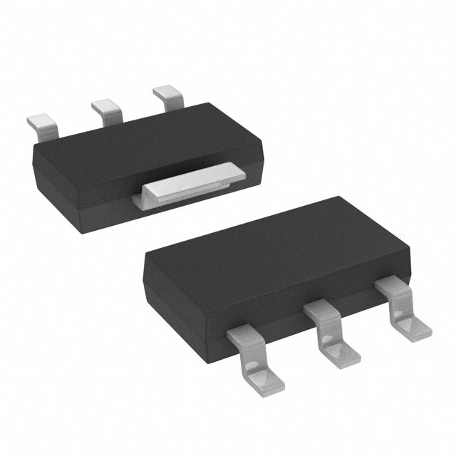 | NCV4274AST33T3G | onsemi | 8,570 | |
 | TPS7B8250QDGNRQ1 | Texas Instruments | 9,770 | |
| TPS7B8150QDGNRQ1 | Texas Instruments | 4,760 |
The A identifies the tighter output-voltage specification. For the 5 V option, the datasheet gives 4.9–5.1 V for the A version and 4.8–5.2 V for the non-A version under the stated input and load combinations. A missing A can therefore change the approved tolerance budget even when the nominal output and DPAK package look familiar. Keep the complete code on the quotation and order. Engineering must explicitly approve a different accuracy version; receiving staff should not treat it as a spelling variation.
No. The manufacturer's AEC-Q100 qualification statement describes the product's qualification context. It does not establish the source or identity of a particular shipment. Likewise, PPAP capable does not mean that a customer's required approval package has already been accepted. Connect the actual lot identifiers, source records, and required approval documents to the purchase requirement. Physical inspection and any electrical screening provide additional observations, but their conclusions must remain within the method and sample scope.
Do not combine the two headline limits into an unconditional operating promise. The 5 V A-version output limits are specified for particular input/load combinations: below 400 mA with input below 28 V, or below 200 mA with input below 40 V, with the other stated lower bounds. Thermal dissipation adds another constraint. A large input-to-output difference creates substantial heat even at modest current. Review the complete electrical conditions and the actual board's thermal capability before approving that operating point.
By Zoey Zhou
The NCV4274ADT50RKG is an onsemi fixed 5 V automotive low-dropout regulator in DPAK, with the A version's 2% output-voltage specification under defined conditions. A purchase decision needs three separate answers: whether the order names the correct device, whether the received lot has the required supply-chain evidence, and whether engineering has approved it for the actual circuit. A matching package photograph or an AEC-Q100 statement cannot answer all three.
That separation matters when a quotation arrives quickly and the production schedule is already tight. A missing character can change the accuracy version. A familiar 400 mA headline can hide a thermal problem. A supplier document can describe the product family while saying nothing about the specific shipment. The useful procurement record connects each claim to the evidence that can actually support it.
Keep NCV4274ADT50RKG intact on the request for quotation, approved bill of materials, purchase order, receiving record, and engineering disposition. Avoid shortening it to NCV4274, NCV4274A, or “5 V DPAK regulator” in fields that control ordering. Those shorter names are useful search terms, but they leave room for a different electrical version, output voltage, package, or packing arrangement.
The onsemi ordering table provides the cleanest identity check. It lists this exact code with 2% accuracy, 5.0 V output, DPAK package, and 2,500 pieces in tape and reel. Those are product attributes. They do not establish how many pieces a supplier currently holds, the condition of a partial reel, or the origin of the offered lot. Keep quotation quantities and manufacturer packing information in separate fields. .
**Figure 1.** Calculated pass-element loss, using P = (VIN − 5 V) × IOUT. The curves exclude ground-current dissipation and do not define a safe operating region or measured board temperature. The fuller thermal calculation must include ground current and the actual thermal path. **Figure 2.** An editorial receiving workflow: verify the exact identity, connect the lot to required evidence, confirm the approved engineering use, and record the disposition. An unresolved requirement returns to hold and clarification; the diagram is not a certification or a prescribed industry standard.For this exact 5 V option, use the relevant electrical-table row. At 1 mA output current, the table gives 190 µA typical and 250 µA maximum ground current. At 250 mA output it gives 10 mA typical and 15 mA maximum; at 400 mA it gives 20 mA typical and 35 mA maximum. Preserve the load and test conditions, and distinguish typical estimates from guaranteed bounds. The generic family headline does not replace the detailed 5 V specification.
No. The reference circuit's nominal capacitance is only part of the selection. Effective capacitance and ESR must remain appropriate over load, temperature, tolerance, and applied voltage. A different capacitor technology can change both values. Review the datasheet's reference circuit, stability plot, and application guidance together, then validate the actual component and layout. Procurement should preserve the engineering-approved requirements instead of treating matching nominal capacitance as proof of electrical equivalence.
No. NCV4274DT50RKG is a non-A accuracy comparator listed in the datasheet's discontinued group. NCV4274AST33T3G has a 3.3 V output and SOT-223 package. TPS7B8250QDGNRQ1 and TPS7B8150QDGNRQ1 are lower-current automotive LDO options in a different package, useful for a deliberate redesign review. Each comparison answers a different engineering question. None establishes pin compatibility, identical capacitor behavior, adequate thermal performance, or approval for the existing board.
Table 1. Identity fields to match before a purchase order is released.
| Field | NCV4274ADT50RKG identity | What the buyer should resolve |
|---|---|---|
| Manufacturer | onsemi | Match the approved manufacturer record and offered documentation. |
| Full orderable code | NCV4274ADT50RKG | Preserve every character; resolve any abbreviated quotation. |
| Electrical version | NCV4274A, 2% output specification | Do not silently accept the non-A accuracy version. |
| Nominal output | 5.0 V | Confirm the board requires the fixed 5 V option. |
| Package | DPAK | Match the approved footprint and mechanical drawing. |
| Packing | 2,500 pieces, tape and reel | Verify the actual delivered quantity and original or partial-reel status separately. |
The A character deserves a deliberate check. In the 5 V electrical table, the A version is specified from 4.9 V to 5.1 V over the stated operating combinations. The non-A version uses a wider 4.8 V to 5.2 V range. That difference can consume a meaningful part of the tolerance budget of a downstream sensor, reference, or logic supply. A receiving team should not decide that the wider range is acceptable simply because the nominal voltage remains 5 V.
Use the ordering table to establish the meaning of the complete code, rather than inventing a universal suffix decoder. Suffix conventions can vary between manufacturers and product lines. The actual table also avoids confusing the package designation with a similar-looking marking printed on a small device. The package marking is intentionally shorter than the orderable part number; it needs interpretation against the correct marking diagram.
A correct marking is one observation, not proof of authenticity. Conversely, a marking that does not reproduce the full purchasing code is not automatically suspicious. Record the observed characters and orientation clearly, compare them with the manufacturer's drawing, and refer unexplained differences to the responsible quality or engineering contact. Guessing what a partly legible character “must mean” weakens the record precisely when it is most needed.
The datasheet identifies automotive applications and describes the device as AEC-Q100 qualified and PPAP capable. These statements support the product's intended qualification context. They do not certify a particular distributor's stock, prove the identity of every received component, or show that a customer's production part approval has been completed. NCV4274/D, features and ordering notes.
Procurement is more effective when each request is tied to a decision. Ask for traceability because the receiving process needs to connect the offered lot to its source. Ask for the required approval package because the customer's release procedure calls for it. Ask for original labeling and packing details because the order specifies them. A generic request for “all certificates” often produces a large attachment set without resolving the important gaps.
Table 2. Different evidence answers different procurement questions.
| Evidence layer | Question it can help answer | What it does not establish alone |
|---|---|---|
| Manufacturer datasheet | What electrical, package, and qualification claims apply to this device? | The provenance or condition of the offered shipment. |
| Approved BOM and drawing | Which exact component and footprint did engineering approve? | That the received material matches the approval. |
| Supplier and source records | How is the offered material connected to an accepted supply route? | Full electrical performance on the customer's board. |
| Lot labels and shipment records | Which material was received, in what quantity, and with which identifiers? | Authenticity solely from label appearance. |
| Customer-required approval records | Has the required project-specific approval been completed? | Approval for every different customer or application. |
| Incoming inspection results | What was actually examined or tested under the stated method? | Unmeasured characteristics or every unit in an unsampled population. |
Agree on the required records before ordering whenever possible. A supplier can then confirm which documents accompany the material and which require additional arrangements. This is easier than discovering, after receipt, that the production release depends on a document nobody included in the purchase agreement. The exact requirement belongs to the customer's quality process; this article does not prescribe a universal automotive receiving standard.
Mixed lots need particular care. If a delivery contains several date or lot codes, keep the identities visible through inspection and disposition. Combining them into one internal bag before the review is complete can make later questions harder to answer. The same principle applies to split reels: record the quantity, source label relationship, and handling information actually available, without describing a re-packed quantity as an untouched manufacturer reel.
Do not fill missing evidence with an assurance copied from a product listing. “AEC-Q100” describes a qualification claim; “PPAP capable” describes capability to support a process. Neither phrase means that a specific customer has accepted a particular lot. When a required approval is absent, the record should say that it is absent and identify the person responsible for resolving it.
Ask the supplier a specific question: “Can you provide the traceability and approval records required by this order for these identified lots?” The answer can be assessed against the purchase requirement. A broad question such as “Is this automotive grade?” leaves too much interpretation on both sides.
Consider a hypothetical delivery with two reels carrying the correct complete part number. One reel has the expected documentation; the other arrives with an incomplete connection between its label and the source record. Matching electrical samples from both reels would not repair the missing documentary connection. The sensible disposition separates the two identified quantities and resolves the missing record under the buyer's quality procedure. It does not imply that the second reel is counterfeit, and it does not allow the first reel's evidence to stand in for it.
This distinction is useful during urgent purchases because it keeps uncertainty precise. The buyer can ask for one missing relationship instead of restarting every check. Engineering can continue reviewing the already identified device. Quality can decide whether the offered evidence satisfies the actual requirement. Clear boundaries make the work faster without pretending that one type of evidence answers a different question.
For the 5 V output option, the operating input range is 5.5 V to 40 V and the junction-temperature range is −40°C to +150°C. The absolute maximum and peak-transient figures appear elsewhere and serve different purposes. A 60 V peak rating is not permission to run the regulator continuously from a 60 V rail. Nor does a 40 V operating limit mean that every combination of current, accuracy, ambient temperature, and board construction is guaranteed at that voltage.
The output-voltage row is more specific. Its 4.9–5.1 V limits apply to the A version for the stated combinations: above 5 mA and below 400 mA with input above 6 V and below 28 V, or above 5 mA and below 200 mA with input above 6 V and below 40 V. Preserve the inequalities when evaluating a boundary case. A load at exactly an endpoint should be reviewed against the manufacturer's complete test conditions, rather than casually rounded into a guaranteed region. NCV4274/D, operating range and electrical characteristics.
Table 3. Electrical values that need their conditions attached.
| Item | Relevant 5 V version data | Procurement or engineering implication |
|---|---|---|
| Operating input | 5.5–40 V | Review the actual input envelope and transient protection separately. |
| A-version output limits | 4.9–5.1 V under the two specified input/load combinations | Do not use “2%” without the operating conditions. |
| Dropout at 250 mA | 250 mV typical; 500 mV maximum | This row is not a 400 mA dropout guarantee. |
| Ground current at 1 mA output | 190 µA typical; 250 µA maximum | The family headline of 150 µA is not the precise 5 V table value. |
| Ground current at 250 mA output | 10 mA typical; 15 mA maximum | Include input-side ground current in heat and power budgets. |
| Ground current at 400 mA output | 20 mA typical; 35 mA maximum | High-load dissipation exceeds the simple pass-element estimate. |
| Current limit | 400 mA minimum, 600 mA typical | A typical limit is not an approved 600 mA continuous load rating. |
Ground current is an easy place to make an otherwise careful comparison misleading. The family features page mentions 150 µA, while the detailed 5 V table gives 190 µA typical at 1 mA load. At heavier loads, the current is specified in milliamperes. A battery drain estimate based on the headline alone can therefore miss both the exact output variant and the relevant operating point.
Use the detailed row that matches the intended load, and retain whether the number is typical or maximum. Typical values help estimate expected behavior under the test conditions. Maximum values are more appropriate when the design needs a guaranteed bound, provided that the row's conditions cover the design. Neither approach justifies extrapolating a current characteristic beyond the region the manufacturer documents.
The dropout specification deserves similar treatment. A successful room-temperature test at a moderate load does not establish the worst-case low-input behavior of every unit. If a system must remain regulated during a supply dip, engineering should review the input waveform, load profile, output tolerance, and dropout conditions together. Procurement can support that review by preventing substitutions that alter those conditions without an explicit decision.
For example, imagine a board that normally runs at 100 mA but briefly reaches 250 mA while another circuit starts. A purchasing description that says only “100 mA application” omits the operating point that may determine dropout and heating during the event. The engineering requirement should include that peak, its duration and repetition, and the minimum input during the same interval. A peak that occurs when the input is already low presents a different regulation question from the same peak at a steady 13.5 V.
No new device limit follows from that example. Its purpose is to show what information must accompany an alternate-part request. If the startup profile is unknown, record it as an engineering input to establish. Do not replace it with the regulator's maximum current headline or a convenient average measured over a much longer interval. The approved component decision should match the relevant time scale of the load.
The part's current rating is only one part of the thermal question. An LDO converts the difference between input and output voltage into heat. At a nominal 13.5 V input and 5 V output, the pass element alone dissipates 2.125 W at 250 mA. That is already substantial for a compact surface-mount package, before adding the power associated with ground current.
The datasheet gives the fuller expression: maximum dissipation equals input-to-output voltage difference multiplied by load current, plus input voltage multiplied by ground current at that load. For an illustrative 13.5 V input, 250 mA output, 4.9 V minimum output, and 15 mA maximum ground current, the calculation is 2.3525 W. This is a screening calculation from specified values, not a measurement of a particular board.

At an 85°C ambient temperature and a 150°C junction ceiling, 2.3525 W requires an effective junction-to-ambient thermal resistance no higher than about 27.6°C/W, even before allowing additional design margin. The datasheet's DPAK value is 70°C/W on its stated minimal-footprint FR4 condition. That comparison should trigger a board-level thermal review; it should not be interpreted as proof that the customer's board has either value.
Copper area, layer connections, neighboring heat sources, airflow, enclosure temperature, and the mounting arrangement all affect the real thermal path. A procurement approval that names only the package loses this context. Engineering should identify the board revision and the validated load/input envelope so that a future sourcing change does not inherit an approval that depended on a different layout.
At 400 mA, using the same 13.5 V input, 4.9 V output bound, and 35 mA maximum ground current produces a screening dissipation of 3.9125 W. This example explains why “400 mA regulator” does not mean “400 mA at any input voltage and ambient temperature.” Thermal shutdown is a protective feature, not a preferred operating mode or a substitute for an adequate temperature margin. NCV4274/D, thermal application guidance.
Capacitors also belong in the engineering approval, particularly when the purchase request includes an alternative part or the board is being reused. The 5 V application circuit shows a 22 µF output capacitor and a 100 nF input capacitor. The datasheet also includes an output-capacitor ESR stability plot and broader application discussion. Treat these as related pieces of design guidance, not as permission to select any nominal capacitance with a similar label.
Actual capacitance and ESR can change with temperature, applied voltage, tolerance, and capacitor technology. A nominal 22 µF marking does not describe the full operating behavior. A change from one capacitor technology to another can alter the effective capacitance and ESR together. Check the chosen component against the relevant stability guidance over the intended load and temperature range, then validate the completed circuit.
The application discussion's general minimum-capacitance and ESR statement should not be detached from the device's reference circuit and stability information. If these details appear to leave an uncertain corner for the proposed capacitor, engineering should resolve it with the manufacturer and appropriate validation. Procurement should preserve the approved capacitor requirements instead of silently treating a cheaper nominal equivalent as an electrical equivalent.
The same discipline applies to layout. Confirm the correct input, ground, and output connections against the pin assignment and package drawing, including the tab connection. A package that fits a pad pattern can still have a different pin arrangement in another product family. Thermal and electrical connections should be reviewed together before a new source or alternate regulator enters the approved BOM.
An incoming inspection plan should begin with what the order requires and what risk the organization needs to resolve. There is no universal sample size or one bench test that establishes everything about a regulator lot. Define the inspection method, acceptance criteria, responsible reviewer, and disposition path before treating a pass result as a release.
For document checks, compare the full orderable code, manufacturer, quantity, packing description, and lot information across the purchase record and received material. Save clear observations where the process requires them. A mismatch should remain visible in the inspection record; editing the receiving description to make it resemble the purchase order destroys useful evidence.
Table 4. A practical receiving review and its decision output.
| Review | Record the actual observation | Escalation or release output |
|---|---|---|
| Order identity | Complete code, manufacturer, package, quantity, and packing | Resolve substitutions or abbreviations before release. |
| Lot and source evidence | Available identifiers and their connection to the accepted supply route | Identify missing evidence and its owner. |
| Physical condition | Packaging condition, label consistency, and any visible damage | Isolate affected material for documented disposition. |
| Marking review | Observed marking compared with the applicable drawing | Refer unexplained differences; do not infer authenticity from appearance alone. |
| Electrical screening, if required | Method, conditions, instrument status, sample identity, and results | Apply the approved acceptance criteria to the tested scope. |
| Engineering fit | Approved board revision, input/load envelope, thermal and capacitor requirements | Obtain explicit approval for any design or part change. |
Electrical screening can answer a narrow question well when the method is clear. For example, a regulated-output check can document output voltage at a defined input, load, and temperature. It cannot, by itself, establish automotive qualification, long-term reliability, the full temperature envelope, or every protection characteristic. The report should name the conditions instead of reducing the result to an unexplained “tested OK.”
Protect the component and the test setup while gathering those observations. Use an approved fixture and controlled supply/load conditions, with suitable current limiting and connection checks. Do not improvise destructive reverse-voltage or short-circuit testing merely because the datasheet lists protective features. Such tests need an engineering-defined purpose and method, especially if tested units might later return to production stock.
Sampling also limits the conclusion. A result from identified samples describes those samples under that method. The organization's quality process determines how it informs acceptance of the lot. The article's workflow does not create a statistical sampling plan, and it should not be used to imply that a handful of room-temperature measurements proves every device is genuine or compliant.

A hold should be specific enough to resolve. “Awaiting engineering confirmation of the non-A substitution” is actionable. “Quality issue” without a description is not. Identify the affected material, the missing or conflicting evidence, the responsible decision maker, and the condition for release. This keeps a supply problem from turning into an undocumented design change.
When a decision is made, preserve its scope. Approval for a particular lot, board revision, and load condition should not automatically become blanket approval for future substitutions. If an exception is accepted, record the exception as an exception. Future buyers and engineers need to see the original requirement as well as the reason the disposition was acceptable in that case.
Related models are useful when they reveal what can change. They are less useful when a comparison table suggests that every automotive LDO is interchangeable. The following four orderable parts illustrate distinct decisions: the wrong accuracy version, a different output rail and package, and two lower-current automotive LDO options. None is offered here as a drop-in replacement.
Table 5. Four related parts and the question each comparison can answer.
| Exact related MPN | Manufacturer | Verified relationship | Boundary before considering a change |
|---|---|---|---|
| NCV4274DT50RKG | onsemi | Non-A 5 V, 4% version in DPAK | Listed in the discontinued group of Rev. 17; a historical mis-order comparator, not a new sourcing recommendation. |
| NCV4274AST33T3G | onsemi | A-version 3.3 V regulator in SOT-223 | Different output and package; relevant to another rail design, not replacement on the existing 5 V footprint. |
| TPS7B8250QDGNRQ1 | Texas Instruments | Automotive 300 mA LDO option with enable in 8-pin HVSSOP | Recheck load capability, output option, pinout, capacitor requirements, thermal design, and approval documents. |
| TPS7B8150QDGNRQ1 | Texas Instruments | Automotive 150 mA LDO option with enable in 8-pin HVSSOP | Suitable comparison only when the load budget allows a lower-current device and a board redesign is acceptable. |
The first comparison is primarily a control against accidental substitution. If a quotation omits the A, the electrical approval should stop and examine the wider output range. Its appearance in the manufacturer's discontinued ordering group also means that a historical listing should not be treated as evidence of a current production supply route. Current lifecycle and sourcing questions require fresh confirmation for the intended purchase.
The 3.3 V NCV4274A option helps when a product revision introduces a different low-voltage rail. It is not a clever way to satisfy a shortage on a 5 V board. Keeping it in the comparison makes the family relationship visible while also making the disqualifying differences explicit. An engineer can decide whether a wider architecture change is relevant; a buyer should not make that change through a substitute line item.
The two TI devices create a different conversation. Their official orderable-part pages identify 300 mA and 150 mA automotive LDO families with enable and an 8-pin HVSSOP package. Those features can be useful starting points for a lower-load design review. They do not preserve the NCV4274A's 400 mA headline or its DPAK footprint. A promising product-page comparison is the start of detailed qualification, not its completion. TPS7B8250QDGNRQ1, TPS7B8150QDGNRQ1.
A useful alternate-part request therefore includes the actual load profile, input range, allowable output tolerance, board space, temperature environment, and required qualification evidence. Without those details, the comparison tends to reward attractive headline numbers while missing the constraint that matters most to the design.
Before release, the record should tell a future reviewer exactly what was accepted. It should identify NCV4274ADT50RKG, the received material and required source evidence, the completed inspection scope, and the applicable engineering approval. Any remaining exception should have a named disposition rather than an implied acceptance hidden in a purchasing email.
Give each team a clear responsibility. Procurement protects the exact identity and the supply record. Engineering defines the valid electrical and thermal use. Quality connects the observations to the organization's acceptance process. The result is a decision another person can understand without reconstructing the whole conversation.
For this device, the details worth protecting are concrete: the A-version accuracy, the 5 V electrical rows, the distinction between operating and peak ratings, load-dependent ground current, the board's thermal path, and the approved capacitor behavior. Connecting those details to the actual lot makes the release record useful long after the order has been received.