
Susanna Feng




| Picture | Part Number | Manufacturer | Stock | Action |
|---|---|---|---|---|
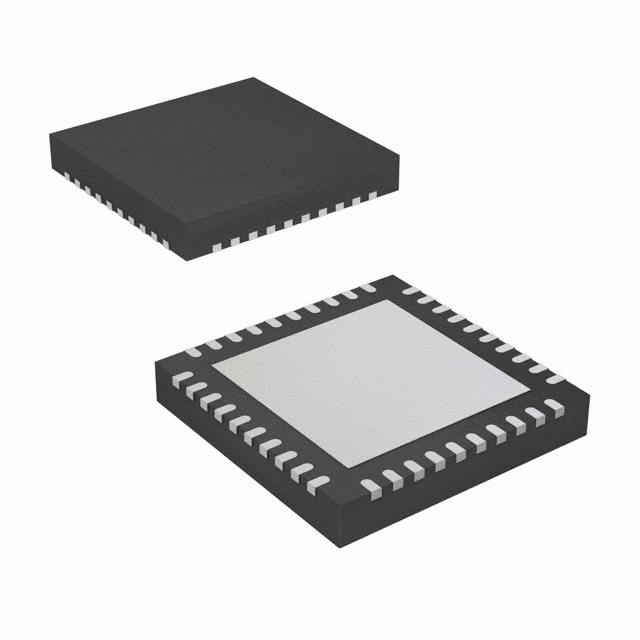 | NCN5130MNTWG | onsemi | 1,690 |
The node needs energy storage, buck power components, decoupling and bus protection. ST recommends a 33 uH inductor with rated current above 150 mA and saturation current above 550 mA, plus rail-specific capacitors. Price those components and their assembly requirements with the transceiver, using the selected circuit and load profile.
ST lists up to 30 mA bus-power extraction, a 20 mA linear output and a 150 mA buck output. The output capability is limited by the allowable bus consumption. Convert each load's voltage and current into a power requirement, include losses and startup, and assess the complete node. Adding the two regulator currents mixes different points in the power path.
ST's startup table specifies at least 100 uF on VDDHV for 10 mA fan-in and at least 220 uF for 30 mA. Preserve the chosen allowance with its storage network. Test the MCU and sensor startup sequence while those capacitors charge, as steady-state current alone leaves that interval unanswered. DS12399 Rev3, Table 7.
Category: Manufacturer Insights
By Susanna Feng
STKNX combines a KNX twisted-pair transceiver, bus-power extraction and two regulators in one STMicroelectronics device. That integration can form the communication and power entry point of a compact node, but it leaves a real supporting BOM. The procurement decision must combine bus-current allowance, output-rail demand, energy storage and protection. Adding regulator current ratings together does not establish the power available to the completed node.
ST specifies a selectable 3.3 V or 5 V, 20 mA linear output, an adjustable 1 V to 12 V, 150 mA buck output and bus-power extraction supporting up to 30 mA. The regulator table explicitly qualifies output capability by the limited consumption available from the bus. The three ratings describe different points in one power path, rather than independent current sources. .
NCN5130MNTWG is an onsemi KNX candidate with embedded PHY/MAC layers and selectable UART/SPI host communication. Its QFN40 package differs from STKNX's 24-pin footprint. A comparison should include host software, regulator arrangement, bus-current requirements and the supporting BOM; it is a node redesign rather than a routine component swap.
ST lists STKNX in tube and STKNXTR in tape and reel. State the production quantity, need-by date and accepted supply form, then confirm pack quantity, MOQ, lot records and delivery basis in the offer. A packing option does not create another transceiver architecture, but it does affect assembly and quotation conditions.
A bus-powered KNX node needs a power budget, not a sum of output-current headlines. List the MCU, sensors and other loads at their actual supply voltages. Include idle, active and startup conditions. This reveals whether the node fits the allowed bus load and whether an integrated output is suitable for the intended load.
Power conversion explains why current alone is an incomplete comparison. A lower-voltage output can deliver a different current from the higher-voltage input while remaining constrained by input power and conversion loss. A linear regulator has a different loss mechanism from a buck converter. Use the actual selected topology and validated operating conditions when converting the node's loads into a bus-current requirement.
For a buyer, the useful deliverable is the declared bus-load requirement paired with the approved rail arrangement. It allows purchasing to compare quotations for the same usable node. A quotation built around the phrase '150 mA regulator' leaves out the input-power constraint and the supporting parts that make that output useful.
The storage requirement changes with the selected bus fan-in. ST's startup guidance pairs a 10 mA fan-in with at least 100 uF on VDDHV, but a 30 mA fan-in with at least 220 uF. That is a concrete BOM difference inside the same transceiver design. Preserve the selected fan-in and its storage network together when calculating node cost. STKNX datasheet, Table 7, page 16.
Table 1. STKNX external-component guidance that affects the node BOM
| Circuit requirement | Manufacturer guidance | Purchasing implication |
|---|---|---|
| 10 mA bus fan-in | CGATE 47 uF; CVDDHV at least 100 uF | Keep the fan-in setting with the approved storage BOM |
| 30 mA bus fan-in | CGATE 10-47 uF; CVDDHV at least 220 uF | A different bus allowance changes the storage requirement |
| Buck inductor | Recommended 33 uH; rated current above 150 mA and saturation current above 550 mA | Inductance alone is an incomplete purchasing specification |
| Buck capacitors | Recommended CIN 10 uF, rated at least 35 V; COUT 22 uF, rated above the chosen output voltage | Preserve rail-specific voltage ratings and accepted effective capacitance |
| Linear/core decoupling | CCORE at least 4.7 uF, rated at least 6.3 V | Retain the stability component even when reducing BOM cost |
Source: DS12399 Rev3, Table 1, pages 5-6; Table 7, page 16; linear-regulator guidance, page 17. Component values depend on the selected node configuration.

Figure 1. STKNX linear and buck outputs share the bus-power constraint. The 20 mA and 150 mA ratings apply at different output voltages and cannot be added to infer available input current or node power. Conceptual power flow. Source: DS12399 Rev3, pages 11-12.
A change in this supporting BOM can alter more than unit cost. Capacitor voltage rating, leakage and effective capacitance matter; inductors have operating-current and saturation requirements. Put the approved component specification on the purchasing record so a nominal capacitance or inductance value cannot stand in for the whole selection.
Protection and assembly also belong in the comparison. ST's external-component list includes the bus protection network, while its layout guidance calls for short power loops and keeping sensitive feedback and soft-start nodes away from the switching node. A cheaper component set that needs another layout or protection trial carries a different engineering cost from a repeat order of the accepted design.
Startup qualification should use the selected fan-in, storage and real load sequence. The MCU and sensors may draw current before reaching their idle state, while the storage capacitors are still charging. Measure the bus and output rails during that sequence as well as after the node settles; a steady-state current result answers only the second question.
Load changes deserve a separate test. A burst of processing or a sensor transition can require energy on a timescale different from the permitted change in bus current. The approved storage and conversion arrangement has to bridge that difference. This is why an acceptable average load is not by itself proof of acceptable transient behavior.
Keep the power result tied to the actual node configuration. A transceiver-only demonstration and a production node with its MCU, sensors and firmware are different test objects. Record the board revision, load states and measurement conditions so that a repeat order preserves the qualified solution.
ST identifies STKNX as KNX-certified and supporting KNX TP1-256 in the datasheet. The finished node has its own implementation and conformity tasks. Retain that product-level evidence alongside the approved circuit, so device certification and node acceptance remain distinct purchasing records.
STKNX alternatives can change how much of the KNX communication stack and power architecture is integrated. onsemi's NCN5130MNTWG is a QFN40 candidate with PHY and MAC layers plus selectable UART/SPI host communication. STKNX's 24-pin footprint and MCU interface represent a different implementation.
Table 2. A distinct KNX transceiver candidate
| Exact model | Manufacturer evidence and comparison value | Boundary before selection |
|---|---|---|
| NCN5130MNTWG | onsemi lists the exact order code in QFN40 and describes embedded PHY/MAC with UART/SPI host communication | Different package from STKNX's 24-lead device; review the host software, communication layers and complete power architecture |
Source: onsemi NCN5130 product overview and orderable-part table, accessed October 14, 2026. This is an architecture comparison; a redesign needs a complete circuit and firmware assessment.

Figure 2. STKNX storage changes with fan-in: 10 mA uses at least 100 uF on VDDHV; 30 mA uses at least 220 uF. The recommended 33 uH inductor also needs rated current above 150 mA and saturation current above 550 mA. Qualify the completed node, not only the transceiver. Source: DS12399 Rev3, Tables 1 and 7.
This candidate belongs on a redesign shortlist because it is a genuine KNX interface device, rather than an unrelated supporting part or another STKNX packing suffix. Its different package rules out a same-footprint substitution. The host software must also reflect the candidate's integrated communication layers and selected UART or SPI interface. Preserve those decisions with the power network, rather than assuming that all KNX interfaces present the same MCU workload.
For an existing STKNX node, retaining the released device and its support components keeps the evaluated bus-current and startup behavior intact. For a new node, compare the host's communication task, board area and power outputs for both architectures. A more integrated interface can move software and component work between the transceiver and MCU; the complete node determines whether that trade-off is worthwhile.
STKNX is a useful integration choice when its communication and bus-powered rail arrangement fit the node. Compare the costed KNX node BOM and its approved operating profile alongside the transceiver quotation. Preserve that complete configuration for an existing node; evaluate the related KNX candidate as a different architecture for a redesign.
The defensible purchasing target is a node that meets its bus-power and communication requirements with an accepted supporting BOM. That is more informative than a chip-price comparison, and it keeps integration value separate from unverified cost savings or finished-product certification.
For the approved node, send YG GROUP an STKNX sourcing enquiry with the required quantity, need-by date, approved ordering/packing requirements and any revision restrictions. If supporting components are also needed, identify their released BOM codes separately. Ask about the proposed lot records and applicable incoming checks; keep the node's bus-current, startup and conformity acceptance with the engineering owner.