
Susanna Feng




| Picture | Part Number | Manufacturer | Stock | Action |
|---|---|---|---|---|
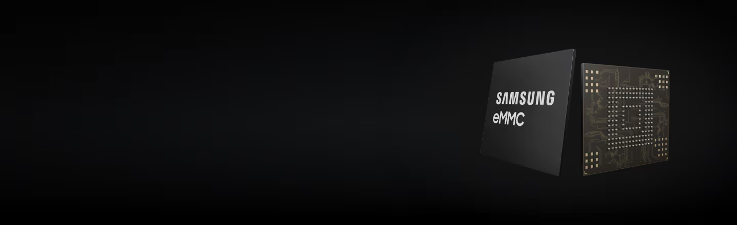 | KLM8G1GEUF-B04Q | Samsung | 7,100 | |
| KLM8G1GEUF-B04P | Samsung | 8,720 |
The general product table lists VCCQ ranges of 1.70–1.95 V and 2.7–3.6 V. However, the documented HS400 mode uses 1.8 V I/O. Choose voltage and operating mode together; the general voltage table does not authorize HS400 at every listed interface voltage. [1, printed pp. 5 and 9]
No. The 400 MB/s figure describes the raw interface-rate calculation. The datasheet reports 40 MB/s sequential write for the 8 GB device under its specified internal-board test conditions, and an application result still needs its own workload measurement. [1, printed pp. 9 and 15]
Do not assume so. The document separately lists user density and describes boot, RPMB and configurable areas. Enhanced-area allocation also affects the capacity available for other purposes. Record the intended device configuration and the actual software layout before accepting the available space. [1, printed pp. 13–15]
By Susanna Feng | Draft revised 21 September 2026
KLM8G1GEUF-B04Q is an 8 GB Samsung automotive eMMC 5.1 device combining MLC NAND and a controller in a 153-ball FBGA package. Its integration decisions involve separate memory and interface supplies, a mode-dependent host interface, and storage configuration that affects usable space. This guide connects the documented requirements to schematic, PCB, firmware and workload checks, with particular attention to the difference between supporting HS400 and demonstrating reliable operation on a particular board. [1, printed pp. 5–9]
The most useful first review is a short list of requirements that affect hardware or software. Samsung's May 2020 Rev. 1.3 Automotive eMMC document explicitly lists KLM8G1GEUF-B04Q in its product table. Its Q temperature option and 8 GB capacity must be kept separate from the other variants covered by the same document. [1, printed p. 5, Table 1]
| Item | Documented value or capability | Integration consequence |
|---|---|---|
| Memory density |
It establishes only what that particular test observed. Review the negotiated interface mode, sustained application traffic, error handling and required recovery cases on the intended hardware/software configuration. The acceptance decision should refer to those records rather than to startup success alone.
| 8 GB; 64 Gb MLC ×1 in the product table |
| Start capacity planning from this device's row, then check the configured user area |
| Package | 153-ball FBGA; nominal 11.5 × 13 × 0.8 mm | Verify the detailed drawing, orientation and ball map before approving the footprint |
| NAND supply, VCC | 2.7–3.6 V | Treat this as a separate supply domain from the host I/O interface |
| Interface supply, VCCQ | 1.70–1.95 V or 2.7–3.6 V | Select the range together with the intended interface mode; the two ranges are not interchangeable for HS400 |
| Q-option operating temperature | −40°C ≤ TC ≤ +105°C | TC is package case temperature, not a blanket ambient-temperature limit |
| HS400 mode | 8-bit DDR, clock up to 200 MHz, 1.8 V I/O | Requires the corresponding host mode, I/O voltage, data strobe and board implementation |
Source: Samsung Automotive eMMC Rev. 1.3, printed p. 5, Table 1 and features; p. 9, HS400 section and Table 4. Values are documented device requirements and capabilities, not YG Group measurements. The package table does not replace the dimensioned drawing on printed p. 7.
The electrical design consequence is immediate: a board can satisfy the general VCCQ range while still using the wrong I/O voltage for its intended high-speed mode. The package consequence is similar: matching the nominal outline does not demonstrate that a library symbol or footprint connects every ball correctly.
Review these three interfaces together. The memory's supply arrangement, PCB connections and selected host mode must describe the same operating configuration. A successful check in one area does not compensate for a mismatch in another.
Samsung's block diagram distinguishes the controller/interface supply, identified as VDD or VCCQ, from the flash supply, identified as VDDF or VCC. It also shows VDDi and its external capacitor connection. Follow those actual signal names when reviewing the schematic; a generic “eMMC power” label hides distinctions that matter to the circuit. [1, printed p. 8, Figure 3]
For the PCB, compare the schematic symbol against the ball-assignment table and drawing rather than relying on the package's ball count. The map identifies CLK, CMD, DAT[7:0], RST_n, supplies, grounds and Data Strobe. In the supplied drawing Data Strobe is H5, CLK is M6 and CMD is M5. Confirm orientation from the manufacturer's view before translating those coordinates into the CAD library. [1, printed p. 6, Table 2 and Figure 1]
Then compare the planned interface mode with the actual host controller and software support. The datasheet specifies HS400 with an 8-bit bus and 1.8 V signaling; its device-type table marks the 1.2 V HS400 option as unsupported. General dual-range VCCQ support should therefore never become an instruction to run HS400 at either available rail voltage. [1, printed p. 9, Table 4]

A practical review output is one controlled configuration record: supply selections, schematic and PCB revision, approved ball map, intended mode, and the host software that selects it. That record makes a later test result meaningful because its hardware and software assumptions are explicit.
HS400 describes how the interface transfers data. It does not promise that an application writes at the interface's theoretical transfer rate. The distinction matters for logging, image storage and other workloads whose sustained writing requirement can be much lower or higher than an optimistic headline suggests.
For an 8-bit interface transferring data on both clock edges at 200 MHz, the raw calculation is 8 bits × 2 × 200 million cycles/s ÷ 8 bits/byte = 400 MB/s. This is an interface-rate calculation; it omits protocol overhead, internal storage operations and software behavior. It is not a benchmark. Samsung's HS400 section describes the corresponding interface mode, while the separate performance table reports device-level results under stated test conditions. [1, printed pp. 9 and 15]
For the 8 GB device, that performance table reports sequential read at 330 MB/s and sequential write at 40 MB/s. The listed conditions are an x8 bus, HS400, 512 KB transfers, packed commands off, cache on, no filesystem overhead, and Samsung's internal test board. These are reported table values under those conditions, not a guaranteed result on an application board. [1, printed p. 15, Table 19]
That gives an engineering team a better question than “Does this part support HS400?” The useful question is whether the complete system sustains its required traffic with its actual request sizes, filesystem, free-space level and background activity. Mode support belongs in the compatibility review; workload acceptance belongs in a separate test record.
HS400 read timing uses Data Strobe. Samsung's timing section describes the strobe's behavior and provides separate device-input and device-output timing diagrams. Do not treat the strobe as an optional decorative signal on a layout intended for that mode, or replace its timing relationship with an assumption based only on CLK frequency. [1, printed pp. 23–24, Figures 6–7 and Tables 26–27]
Loading requirements also depend on the mode. The document places general bus-loading information and HS400-specific capacitance/resistance information in separate tables. Retain that distinction when reviewing board loading, pull-ups and the data-strobe connection. [1, printed p. 27, Tables 36–37]
This article does not supply a universal trace-length rule or a validated layout. Those decisions require the host documentation, interconnect properties and the actual board. A useful review records which requirement controls each signal group, how the PCB meets it, and which measurement or analysis will confirm the timing margin. A generic statement that the board “uses eMMC routing” is too vague to audit.
The capacity printed in a product table is not the same field as the user area available to the application. Samsung describes two boot partitions, an RPMB partition and a user data area, together with configurable general-purpose and enhanced areas. The Rev. 1.3 table lists 7,818,182,656 bytes of user density for the 8 GB device. That number is a device-document value; it is not a prediction of the free space a formatted application will report. [1, printed pp. 13–15, section 6.1 and Table 18]
Enhanced-area allocation has a real capacity cost. The document describes using SLC mode for enhanced user storage and explains that allocating enhanced storage consumes twice the original MLC area in its stated example. Consequently, enhanced-area planning belongs before application capacity is signed off. It cannot be treated as a performance option with no space tradeoff. [1, printed p. 13, section 6.1.1.1]
Have firmware and manufacturing agree on the required boot arrangement, RPMB use, general-purpose partitions and enhanced allocation before provisioning devices. The register tables distinguish read-only, writable and one-time-programmable behavior; an exploratory configuration change should not be assumed reversible. This is a planning recommendation, not a command sequence for changing a device. [1, printed pp. 17–21]
Keep three values separate in the release record: the nominal device density, the configured device areas and the application's reported usable space. If they differ, that difference should be explainable from configuration and software, not hidden by copying “8 GB” into every field.
Choose an acceptance question before choosing a benchmark. For example, an embedded logging design might need to sustain its incoming records while completing housekeeping, restarting cleanly and recovering according to its data-integrity requirements. This is a proposed use case for evaluation, not a claim that Samsung or YG Group validated a particular logging product.
The manufacturer's sequential-performance conditions provide a reference point for documenting a test, not a reason to reproduce only the most favorable setting. Use the actual request sizes, access pattern, storage occupancy and software stack of the intended system. If a filesystem is part of the product, include it in the application test even though the datasheet's performance table excludes filesystem overhead. [1, printed p. 15, Table 19]
| Review area | What to record | Why it matters |
|---|---|---|
| Platform | Host, PCB revision, device identity and firmware/software builds | Keeps results tied to the system that produced them |
| Operating setup | Supply configuration, selected host mode and temperature conditions | Distinguishes a setting from an actually observed operating state |
| Workload | Request size, access pattern, read/write mix and run duration | Makes the application requirement reproducible |
| Storage state | Partition configuration, occupancy and relevant cache settings | Exposes configuration differences between runs |
| Observed behavior | Throughput, latency distribution, errors and recovery observations | Prevents an average rate from hiding a failed operation |
| Changes | Configuration or software changes between runs | Explains why two apparently similar tests differ |
This is an original YG Group test-record template informed by the conditions in Samsung Rev. 1.3, Table 19. It contains no performed test or measured result.

Include the interruptions relevant to the finished product. A clean startup alone says little about an interrupted write or a host reset while storage remains powered. Define the permitted recovery behavior with the applicable device and system requirements, then record what happens. Cache support or managed NAND architecture should never be turned into an unsupported promise that every recently issued write survives arbitrary power removal.
The Q entry in the product table specifies −40°C to +105°C for TC. The corresponding P entry specifies −40°C to +95°C for TC. A comparison that reports only “automotive eMMC” loses this documented distinction. [1, printed p. 5, Table 1 note]
KLM8G1GEUF-B04P is therefore a relevant same-family comparison, but this article does not recommend it as a drop-in replacement. Its listed upper case-temperature boundary differs. Likewise, KLMAG2GEUF-B04Q is a documented 16 GB family member; a larger density does not independently establish interchangeable firmware behavior, configuration or acceptance results. [1, printed p. 5]
The automotive document title and the temperature table do not establish a particular application's safety qualification, an AEC-Q100 grade, a current lifecycle status or the history of a supplied lot. Those are separate evidence questions. Keeping them separate makes both engineering and purchasing decisions clearer.
An effective KLM8G1GEUF-B04Q integration review connects the documented part to a specific board and software configuration. Approve the supplies and ball map, confirm the host mode, plan the storage areas, and retain workload and recovery evidence. The result is a reproducible engineering decision whose limits are visible—not simply a copied specification table.