
Carmen Lau



6 views

| Picture | Part Number | Manufacturer | Stock | Action |
|---|---|---|---|---|
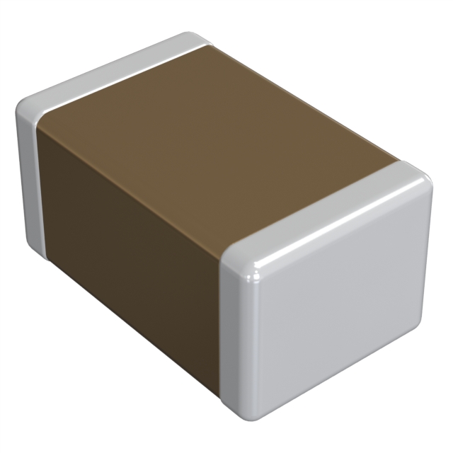 | GRM155C81E105KE11D | Murata | 5,250 |
 | GRM155C81E105KE11J | Murata | 9,000 |
No. Initial capacitance tolerance and the temperature characteristic describe different measurements. Use the specified initial-measurement conditions and the separate temperature-change definition, then evaluate the circuit under its relevant conditions.
Not from this product summary. Its notes identify a limited summary and characteristic information. A guaranteed minimum for a design decision requires the applicable specification and the relevant conditions, rather than an isolated typical plot value.
No. A voltage rating and a capacitance-versus-bias characteristic answer different questions. A circuit may remain within a voltage rating while still needing a separate effective-capacitance assessment.
The cited sheet presents D and J as packaging codes. It does not identify J as a higher temperature grade. Keep the packaging distinction in procurement records without inventing an electrical upgrade.
By Carmen Lau
GRM155C81E105KE11D is a Murata GRM ceramic capacitor whose published product sheet identifies an X6S temperature characteristic. That characteristic answers a different question from the part's initial capacitance tolerance. Understanding the distinction helps an engineer decide whether a temperature requirement is compatible with the capacitor, what needs checking on the board, and which conclusions still require detailed specifications rather than a product-summary curve.
Murata's part-specific sheet lists 1.0 µF with ±10% capacitance tolerance, a 25 VDC rating, and X6S with ±22% capacitance change over -55°C to +105°C. It separately lists the same operating temperature range. The sheet names both the complete D and J ordering codes; D denotes 180 mm paper-tape packaging, while J denotes 330 mm paper-tape packaging. These are specifications in a dated product summary, not confirmation of present production or availability. Murata capacitor data sheet, page 1, updated January 25, 2020; manufacturer-authored copy hosted by Octopart.
The useful distinction is between a starting value and a change from that starting value. Initial tolerance describes the allowed difference from nominal capacitance under the specified measurement conditions. Temperature change describes how capacitance moves relative to its reference-temperature value. Treating both percentages as a single tolerance loses that distinction.
| Question in a design review | Evidence to use | Mistake to avoid |
|---|---|---|
| Does the selected temperature category cover the intended conditions? | The exact part's operating and temperature-characteristic ranges | Reading an X6S label as permission to operate beyond its listed range |
| Is an incoming capacitance measurement acceptable? | The detailed measurement method and initial tolerance | Comparing an arbitrary meter setting with the nominal value |
| How does capacitance change as temperature changes? | Temperature-characteristic definition and applicable data | Applying initial tolerance as the entire temperature budget |
| Will the circuit retain enough capacitance in service? | Circuit requirement and data under relevant voltage, temperature, and measurement conditions | Using the temperature category as a complete effective-capacitance model |
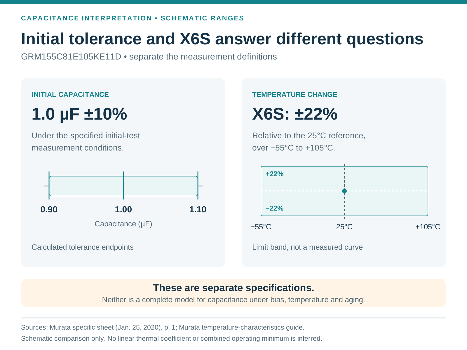
Class 2 ceramic capacitance need not change linearly with temperature. Murata explains its temperature characteristic as a maximum and minimum change within the applicable range, relative to capacitance at the EIA reference temperature of 25°C. That differs from expressing a nearly linear Class 1 characteristic in ppm/°C. Murata, “What is the temperature characteristics of ceramic capacitors?”, revised December 1, 2023.
Consequently, an engineer should not divide the allowed percentage by the total temperature span and create a per-degree correction factor. Such a calculation would invent a curve shape. It could make an intermediate temperature look safer than either the available characteristic data or the manufacturer's limits justify.
For a thermal review, define the question first. A screening question asks whether the intended temperature range fits the listed category. A circuit-performance question asks whether the capacitance available at relevant conditions meets the circuit's requirement. Passing the screening question does not automatically answer the performance question.
This distinction is useful when a board must operate across several environments. A bench measurement near room temperature, a cold start, and a fully warmed enclosure are different operating cases. A single successful test cannot establish the behavior of all three. The engineering task is to identify the conditions that could change the decision, then obtain data for those conditions.
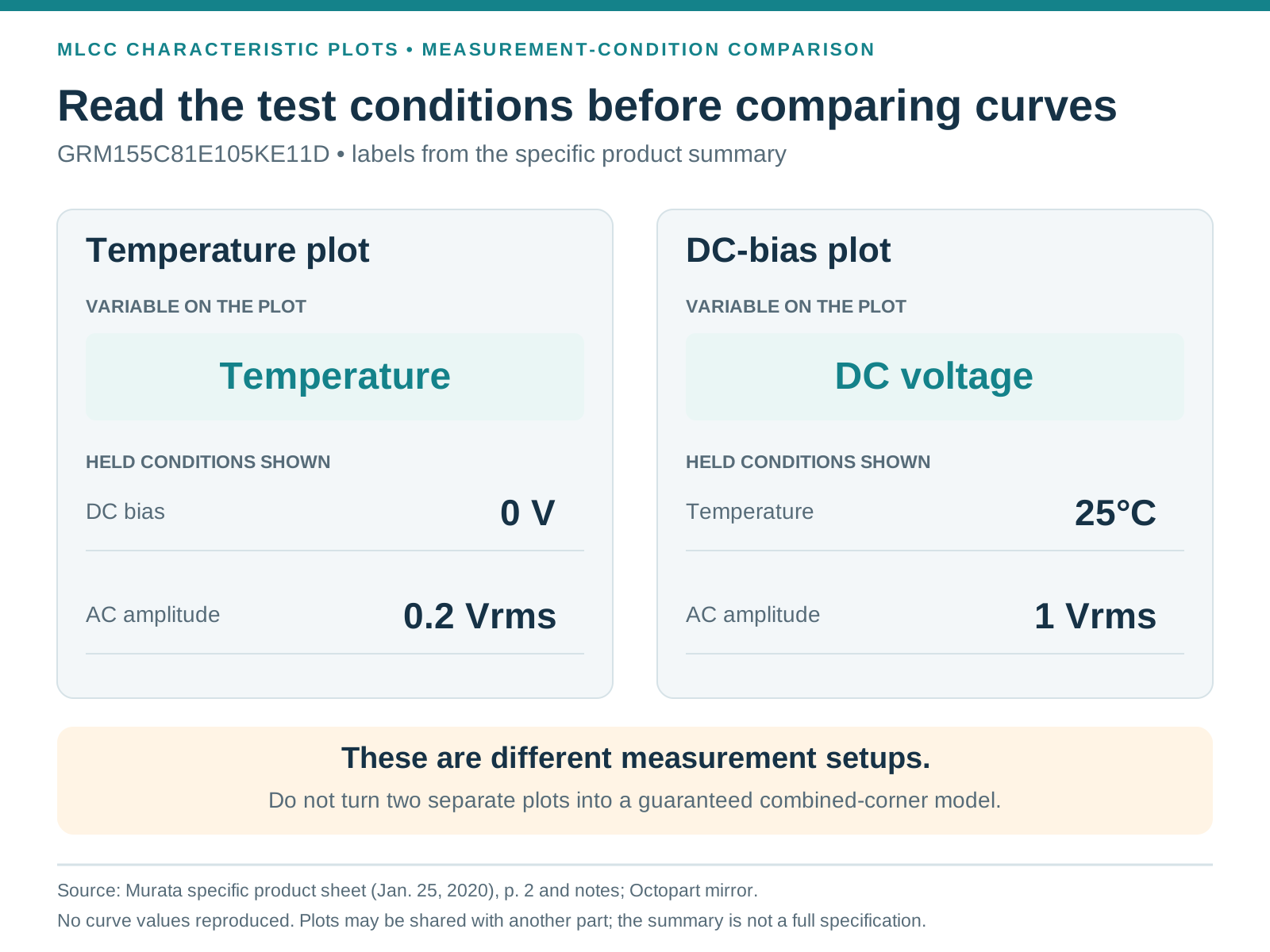
The specific sheet's second page contains capacitance, impedance, resistance, and ripple-heating plots. Its temperature plot identifies zero DC bias and an AC measurement amplitude of 0.2 Vrms. The DC-bias plot instead identifies 25°C and 1 Vrms. The sheet also warns that characteristic plots can be shared with another part number and that the summary does not contain the complete specification. Murata data sheet, page 2 and its notes.
Those labels matter more than a quick reading of the vertical axis. A plotted value that differs from the nominal capacitance does not, by itself, show that the part failed its initial tolerance. First establish whether the graph and the acceptance test use the same conditions. Conversely, a favorable point on a typical curve is not evidence that every delivered part must meet that value.
Before using a graph in a calculation, record four items beside it:
If any item is missing, the calculation has an unresolved assumption. Keep that assumption visible instead of replacing it with a convenient default.
The review should use the temperature requirement at the component location, with the applicable specification's temperature definition. An enclosure's ambient requirement alone is not a complete record of what happens beside a regulator, processor, or another heat-producing component.
Create a thermal evidence record for the capacitor location. Include the expected environments, board operating states, installation constraints, measurement location, instrument method, and observed temperatures when testing is performed. Distinguish a prediction from a measured result. A simulated board temperature can guide testing, but it should not be relabeled as a completed hardware measurement.
For a simple margin calculation, suppose a design review uses a hypothetical maximum component temperature of 95°C. Comparing that assumption with the sheet's listed 105°C upper limit leaves 10°C of arithmetic margin. This is only an example of bookkeeping. It does not establish a permitted temperature rise, a reliability margin, or a qualified operating point for a particular board.
The next question is what could consume that margin. Record uncertainty in the thermal estimate, the range of operating states, and any conditions excluded from the first test. This turns “the temperature looks acceptable” into a reviewable engineering statement.
The product summary also carries a “Derating1” notice without reproducing the complete associated conditions. Obtain the applicable detailed specification and derating instructions before treating the voltage and temperature ratings as a complete simultaneous-use envelope. The summary alone is not a design-release document.
An X6S classification does not specify capacitance under every combination of voltage, temperature, frequency, and time. Murata distinguishes high-dielectric-constant ceramics from temperature-compensating ceramics, including their DC-bias and aging behavior. Its guidance places Class 2 parts in applications such as bypassing, smoothing, and decoupling, while the suitability of any particular part remains a circuit decision. Murata ceramic-capacitor characteristics FAQ.
Keep the temperature budget separate from the other evidence until there is a justified way to combine them. A temperature curve measured at one voltage condition and a bias curve measured at one temperature are not automatically a validated two-dimensional model.
For example, a circuit that needs a minimum capacitance at its hottest operating condition also needs evidence for the applied voltage at that condition. Neither a room-temperature bias plot nor a zero-bias temperature plot answers the combined question alone. It would be equally misleading to use the nominal value throughout the calculation or to multiply unrelated typical reductions and call the result a guaranteed minimum.
Murata's DC-bias guidance explains that applied DC voltage can change the capacitance of high-dielectric-constant ceramics and recommends checking suitability under actual equipment conditions. That supports checking the interaction; it does not supply a universal derating percentage for this part. Murata DC-bias FAQ.
A useful release record ties the exact order code to the circuit decision. It should be understandable to someone who did not create the original schematic.
| Record | What to capture | What closes the review |
|---|---|---|
| Part identity | GRM155C81E105KE11D, manufacturer, approved documentation revision | The order code and supplied documentation refer to the same intended component |
| Circuit requirement | Function and the capacitance or impedance requirement at relevant conditions | The requirement is explicit and has an engineering owner |
| Thermal conditions | Component-location requirement, operating cases, and test or analysis method | The applicable temperature limits and remaining uncertainty are understood |
| Electrical conditions | Applied voltage and the measurement conditions used to evaluate capacitance | Conditions in the evidence correspond to the intended use, or their differences are resolved |
| Assembly packaging | Required reel format and procurement code | Purchasing and assembly agree on the orderable packaging |
| Remaining restrictions | Detailed-specification, derating, and verification requirements | No unresolved restriction is being represented as a completed qualification |
The related GRM155C81E105KE11J is useful here as a packaging comparison because the same specific sheet explicitly lists it. It should not become a reason to omit the full order code from purchase or assembly records. Record the required packaging even when the product summary presents the electrical characteristics together.
A sourcing record should also separate technical approval from commercial status. An old product sheet establishes what that document says about the device. It does not establish current stock, authorized supply, lead time, or the validity of a particular lot. Those questions need their own dated evidence.
For GRM155C81E105KE11D, start by separating initial tolerance, temperature change, and the actual circuit requirement. Read curve conditions before using plotted values, identify the thermal conditions at the component, and obtain the detailed specification and derating requirements for release. The resulting record should explain why the chosen part meets the intended task and which evidence supports that decision, rather than relying on the X6S label alone.