
YG GROUP




No. This article's technical and lifecycle baseline is the Diodes Incorporated model described by DS23016 Rev.15-4. Other manufacturers' similar names have their own order codes, limits and lifecycle records. Attach the maker to every comparison row and quotation so that a favorable parameter from one document is not accidentally assigned to another device.
No. The supplied table lists 10 A per leg and 20 A total under the stated rating conditions. The actual circuit determines the waveform and dissipation in each leg. Do not use the total entry to justify exceeding a leg's rating, and do not interpret either number as an unconditional free-air current capability.
Yes. Its first-page obsolete notice directs the 60 V model toward MBR2060C. That establishes a same-brand comparison direction, not a completed replacement qualification. Read the follow-on's own document and verify pinout, electrical limits, mounting and application behavior before releasing the change.
No. The typical RθJA entry is associated with a specified 45 × 20 × 12 mm heatsink arrangement in note 5. An unheatsinked PCB or a different mounting system needs applicable thermal evidence. Also keep junction-to-case and junction-to-ambient values separate; they are not two numbers to add as consecutive segments.
No direct-substitution recommendation is made. It is included only as an ultrafast PN technology counterexample. Different recovery and switching behavior can matter even when voltage and current headlines appear ample. A technology change requires its own circuit-level loss, stress and thermal qualification.
The reviewed Diodes document and original archive establish that this model is obsolete, but they did not provide a verified exact last-time-buy date for this review. Do not infer one from the document revision or from another manufacturer's product status. Historical lifecycle and present seller availability remain separate records.
Author: YG Group | Category: Manufacturer News & PCN/EOL | Primary part: MBR2060CT | Manufacturer: Diodes Incorporated | Updated: 2026-09-10 | Adapted: 2026-09-15
MBR2060CT from Diodes Incorporated is a discontinued dual Schottky rectifier with a 60V reverse-voltage rating and 10A average-current rating per diode leg. The supplied TO-220AB datasheet directs readers toward MBR2060C, while similarly named devices from other manufacturers require their own qualification. This guide compares the electrical, pinout and thermal evidence needed before choosing a follow-on device or a cross-brand redesign candidate.
Qualify a replacement against the rectifier's actual operating conditions, not against the MBR2060CT name alone. Manufacturer identity, current distribution between the two legs, reverse stress and the mounting arrangement all affect the decision.
Jump to identity, , , , , or .
*Figure 1: Forward and reverse electrical limits have different temperature tradeoffs | Source: [Diodes DS23016 Rev.15-4, p2](https://www.diodes.com/datasheet/download/ds23016.pdf) | Chart: YG Group* *Figure 2: Thermal reference locations and the conditioned heatsink arrangement | Source: [Diodes DS23016 Rev.15-4, p2, note 5](https://www.diodes.com/datasheet/download/ds23016.pdf) | Chart: YG Group*Start with the manufacturer and the supplied document revision. The relevant source is Diodes DS23016 Rev.15-4, dated December 2019, which marks the listed parts obsolete and directs readers toward newer MBR2045C or MBR2060C devices.
For the 60 V model discussed here, MBR2060C is the relevant same-brand follow-on direction. Diodes' inactive datasheet archive, checked on September 10, 2026, also records MBR2060CT as obsolete. That supports the maker-specific lifecycle statement. The reviewed sources do not establish an exact formal discontinuance announcement date or a last-time-buy deadline, so this article does not invent either.
| Identity field | Evidence used | Scope | What it does not prove |
|---|---|---|---|
| Manufacturer | Diodes Incorporated branding on DS23016 | The primary model in this article | Another maker's ratings or lifecycle |
| Model | MBR2060CT | 60 V dual common-cathode Schottky | A fully selected purchasing carrier |
| Package | TO-220AB | MBR2060CT | The insulated MBRF package's thermal behavior |
| Document | DS23016 Rev.15-4, December 2019 | Supplied technical baseline | A new 2026 electrical revision |
| Ordering example | MBR2060CT-LJ; 50 pieces per tube | Historical ordering row | Current packaging availability or a selected user order |
| Lifecycle evidence | Obsolete banner and original archive | Diodes model; archive checked September 10, 2026 | Exact last-time-buy date or zero remaining stock |
| Follow-on direction | MBR2060C | Same-brand potential alternative | Automatic pin, thermal or application equivalence |
Table 1: Manufacturer, model and lifecycle evidence before a replacement search | Source: Diodes DS23016 Rev.15-4 and inactive datasheet archive | Compiled by: YG Group
The unsuffixed model and the carrier-specific order serve different purposes. The user-specified MBR2060CT identifies the device being evaluated. The document's MBR2060CT-LJ row adds a purchasing and packaging detail. Preserve that distinction until the required carrier is selected; silently appending a suffix would turn a technical comparison into an unsupported order decision.
Next reconcile the old bill of materials, approved-source list and assembled-board marking. If several manufacturers were historically allowed, establish which qualification record applies to each. A spreadsheet row containing only MBR2060CT may conceal multiple independently specified devices. The remedy is not to choose the most favorable number from their datasheets; it is to build a manufacturer-specific baseline for the installed design.
This approach also changes the sourcing conversation. Ask whether the project is maintaining an existing qualified assembly or redesigning it for future production. The first question may involve dated availability and traceability for the original part. The second requires candidate qualification and a released change. A current offer for the discontinued model does not answer how much redesign work another rectifier will require.
Read the per-leg and total entries together with the waveform and thermal context. The 60 V reverse rating, 10 A average rating per leg and 20 A total are different constraints, not interchangeable descriptions of a single guaranteed board capability.
The maximum-rating table is headed “Per Leg” and uses single-phase, half-wave, 60 Hz resistive or inductive loading, with a stated 20% current derating for capacitive loading. Its nonrepetitive surge entry is an 8.3 ms single half-sine superimposed on rated load. These conditions must remain attached when the original device is compared with a candidate. DS23016, p2.
| Parameter | Rating basis | Documented value | Condition or interpretation |
|---|---|---|---|
| Peak repetitive reverse voltage | MBR2060CT leg | 60 V | Check actual reverse waveform, including switching excursions |
| Working peak reverse/DC blocking voltage | MBR2060CT leg | 60 V | Not permission to exceed the rating during normal operation |
| Average rectified output current | Per leg | 10 A | Stated half-wave 60 Hz load conditions and thermal limits apply |
| Average rectified output current | Total | 20 A | Do not assign the total independently to both legs |
| Nonrepetitive peak surge | Per-leg maximum-rating scope | 180 A | 8.3 ms single half-sine superimposed on rated load |
| Capacitive-load adjustment | Current-rating note | Derate current by 20% | Apply the document's load qualification, not a universal switching rule |
| Junction/storage range | Device thermal limit | −55°C to +150°C | Not an allowable ambient range at arbitrary dissipation |
Table 2: Per-leg, total and waveform-conditioned ratings | Source: Diodes DS23016 Rev.15-4, p2 | Compiled by: YG Group
A dual common-cathode package does not force the two legs to share current in a particular way. The circuit determines which leg conducts, for how long and with what peak and average current. An alternating rectification arrangement and a design using only one leg therefore need different current records. Before comparing candidates, draw the current path in each switching or line-cycle interval and identify the stress on each physical junction.
Do not treat the 180 A surge entry as a recurring pulse-current rating. A different pulse width, repetition rate, initial junction temperature or preceding load changes the qualification question. If the application has repetitive inrush or fault pulses, obtain the corresponding manufacturer limits or application guidance for the actual waveform. A single headline surge number does not establish that a repeated operating mode is acceptable.
Similarly, a 60 V rating is not a recommended design operating voltage. Record the maximum reverse voltage expected across each leg under normal operation, startup, load release and fault recovery. Include the effect of parasitic inductance and the clamp or snubber arrangement where applicable. The necessary design margin belongs to the project's requirements and evidence; this article does not choose a universal percentage that would fit every topology.
For a practical worksheet, suppose a hypothetical circuit uses one leg for a recirculating-current interval and leaves the other unused. Record the conducting leg's current waveform and the unused leg's reverse bias separately. Do not justify 15 A average through the active leg merely because 15 is below the package's 20 A total entry. The per-leg limit remains part of the evaluation, and the temperature resulting from the actual waveform must still be checked.
An asynchronous buck, such as a design using LM2595S-3.3, provides useful application context for catch-rectifier selection. That context is not a recommendation to install this particular dual rectifier in that converter. Use the application to identify current and reverse-voltage intervals, then qualify the selected rectifier with its own data.
Compare forward drop and reverse leakage at the same stated conditions, but do not assume that improving one number improves every operating mode. The supplied MBR2060CT table gives a lower maximum forward drop at 125°C than at 25°C while allowing a much larger maximum reverse current at the higher temperature.
| Junction temperature | Maximum VF at IF = 10 A | Maximum IR at VR = 60 V | Test interpretation |
|---|---|---|---|
| 25°C | 0.81 V | 0.1 mA | Per-leg electrical limits; not measured board loss |
| 125°C | 0.69 V | 15 mA | Same current/voltage reference points; temperature remains explicit |
Table 3: Forward-voltage and reverse-current maxima at two junction temperatures | Source: Diodes DS23016 Rev.15-4, p2, Electrical Characteristics and note 6 | Compiled by: YG Group
Note 6 specifies a short-duration pulse test for reverse current to reduce self-heating. That matters because the table separates the electrical condition from the temperature rise that a continuously biased application might create. Do not read the 125°C row as a promise that the installed junction will stay at 125°C while dissipating power.
For an arithmetic illustration at the stated 10 A test current, multiplying the 25°C maximum VF by current gives 0.81 × 10 = 8.1 W per conducting leg. Using the 125°C maximum gives 6.9 W. These are products of specified electrical values at fixed junction temperatures, not predictions of a board's steady operating loss. The junction temperature and conduction waveform must be solved or measured consistently with the thermal path.
If a deliberately simplified example assumes 10 A rectangular conduction for 40% of a cycle, using the same constant 0.81 V value gives an illustrative average forward-loss term of 3.24 W. This assumes a fixed drop, neglects current ripple and ignores switching-related loss. It is useful for showing why conduction duty matters, but the electrical table does not establish a maximum VF at every point on an arbitrary current waveform.
The reverse-current products reveal a different constraint. At the stated 60 V reverse bias, 0.1 mA corresponds to 0.006 W, while 15 mA corresponds to 0.9 W, each at its respective specified junction temperature. If reverse bias is present for only part of a cycle, a duty-weighted estimate must reflect that interval. These products are not complete converter losses and should not be combined as if forward and reverse bias occur simultaneously in one junction.
This distinction is valuable during a cross-brand comparison. A candidate may advertise a favorable typical forward voltage while the baseline table supplies a maximum; those entries are not like-for-like. Record whether each figure is typical or maximum, the test current or voltage, junction temperature and test method. If a common-condition comparison cannot be made from the available data, leave that comparison unresolved rather than ranking the parts with mismatched numbers.
At 10 A, the maximum VF values are 0.81 V at 25°C and 0.69 V at 125°C. At 60 V, the maximum IR values instead rise from 0.1 mA to 15 mA at those temperatures. The lower forward-drop limit at the hotter test point therefore does not establish lower overall loss. These are separate electrical limits, not one combined performance score or a defined response at intermediate temperatures.

A Schottky candidate such as PMEG100T100ELPE-Q raises the same loss, leakage and thermal questions. Its package, qualification and ratings do not transfer to Diodes MBR2060CT. The useful shared task is to compare the candidate where the circuit operates, not where a headline parameter looks most attractive.
Recreate the actual junction-to-environment path and verify the electrical connections before treating a candidate as usable. A familiar TO-220 outline and a low thermal-resistance number do not establish either condition.
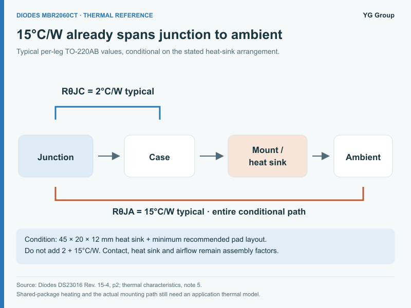
For the MBR2060CT TO-220AB package, the supplied per-leg thermal table lists typical RθJC of 2°C/W and typical RθJA of 15°C/W. Note 5 specifies a device mounted on a 45 × 20 × 12 mm heatsink with the stated minimum recommended pad layout. The RθJA value is therefore tied to that arrangement; it is not a free-air rating for an arbitrary PCB. DS23016, p2.
| Item to verify | Documented baseline | Source condition | Candidate/board check |
|---|---|---|---|
| Electrical topology | Dual common cathode | Diodes MBR2060CT | Verify the candidate's complete internal connection diagram |
| Lead mapping | Pins 1 and 3 are anodes; pin 2 is common cathode | Package diagram, p1 | Use the correct viewing direction and physical orientation |
| Package | TO-220AB | Main MBR model | Check dimensions, lead pitch, mounting and electrical tab/isolation requirements |
| RθJC | 2°C/W typical | Per-leg TO-220AB row | Not a complete junction-to-ambient path or a guaranteed maximum |
| RθJA | 15°C/W typical | Specified 45 × 20 × 12 mm heatsink arrangement | Do not apply directly to an unheatsinked board |
| Insulated package contrast | ITO-220AB: 4°C/W RθJC and 25°C/W RθJA, typical | Separate MBRF package rows | Do not substitute these values into the main device model |
| Remaining thermal path | Mounting interface, heatsink and environment | Application-specific | Establish contact, airflow, nearby heating and both-leg operation |
Table 4: Pinout and thermal-path checks before installing a candidate | Source: Diodes DS23016 Rev.15-4, pp1–2 and note 5 | Compiled by: YG Group
Suppose an illustrative single-leg screening case uses 3 W dissipation and 50°C local ambient. Applying the stated typical 15°C/W arrangement gives a simple estimate of 50 + 3 × 15 = 95°C junction temperature. The calculation is valid only as a simplified estimate using that conditioned thermal number. It does not qualify an actual board, establish a worst-case maximum or describe simultaneous heating in both legs.
At the same assumed 3 W, multiplying by the typical 2°C/W junction-to-case value gives a 6°C rise above the case for that simplified leg model. It does not give a 6°C rise above ambient. The case must reject heat through the mounting and heatsink system, and its temperature may also reflect the other leg and surrounding components.
The same example can be worked backward as a requirement. If the project deliberately chooses a 125°C junction target at 50°C local ambient and assumes 3 W total loss for its screening model, the permitted effective junction-to-ambient resistance is (125 − 50) / 3 = 25°C/W. The 125°C target is an example design choice, not a new device rating. This calculation tells the designer what the complete thermal system must achieve; it does not prove that a particular heatsink achieves it. Recalculate when the loss estimate, local ambient or operating policy changes.
Do not add 2°C/W and 15°C/W as two series segments. Junction-to-ambient already describes an overall path under its stated arrangement, whereas junction-to-case is a different thermal reference. For a detailed model, obtain compatible thermal data and define each reference location. Mixing complete-path and partial-path figures can count the same thermal segment twice.
The dual structure deserves special attention. Both junctions share the physical package and can affect the case temperature. A model that treats each leg as thermally isolated may understate heating when both operate. Use the manufacturer's applicable modeling guidance and actual board validation for the chosen waveform; the short summary table is not enough to invent an independent two-junction thermal network.
Junction, case, mounting interface/heatsink and ambient are distinct thermal reference locations. The 2°C/W typical RθJC and 15°C/W typical RθJA retain their per-leg definitions and stated mounting conditions; neither supplies every segment of an arbitrary board's thermal path. Interface resistance, heatsink performance and the local environment therefore require compatible evidence before this reference arrangement can support an application-specific temperature estimate.
During physical inspection, confirm package orientation against the drawing before connecting power. Check mounting clearances, required insulation and how the candidate's tab is electrically connected; do not infer isolation from a broadly similar plastic shape. A mechanical substitution can change both the thermal interface and the circuit connection, so those reviews should not be separated into unrelated approvals.
For a repeatable sample review, begin with an unpowered orientation and continuity check appropriate to the circuit. Then bring up the assembly under controlled conditions within the defined operating envelope. Record each leg's current waveform, reverse-voltage waveform, case temperature and local ambient at identified observation points. Specify how long the system runs before a steady-state reading is accepted. A temperature recorded during the first seconds of operation answers a transient question, not necessarily the continuous-duty question.
Instrument loading and probe placement belong in that record. A voltage waveform measured through a large probing loop can contain artifacts that look like device stress, while a temperature measurement at a nearby heatsink point may not represent the package case. Document the method and uncertainty rather than presenting every displayed digit as a precise junction measurement. If junction temperature is inferred from a thermal model, label it as inferred and retain the model's conditions.
Start with the original manufacturer's MBR2060C direction, then compare other devices only where they address the same requirement. Preserve the distinction between a potential alternative, a comparison candidate and a technology counterexample.
| Manufacturer and model | Relationship | Relevant technology/context | Qualification still required |
|---|---|---|---|
| Diodes MBR2060CT | Primary baseline | Discontinued dual Schottky; carrier not selected | Establish actual circuit stresses and qualified mounting |
| Diodes MBR2060C | Potential alternative; technical reference | Same-brand follow-on named by the original document | Its own pinout, limits, package and thermal conditions |
| onsemi MBR2060CTG | Potential alternative | Cross-brand 60 V dual Schottky comparison | Exact onsemi order, lifecycle and electrical/thermal data |
| ST STPS20L60CT | Comparison candidate | Dual Schottky candidate | Candidate-specific loss, leakage, pinout and mounting review |
| ST STTH6002CW | Technology comparison only | Ultrafast PN rectifier, not a Schottky equivalent | Switching/recovery behavior and full redesign; not a recommended direct substitute |
Table 5: Same-brand and cross-brand relationships with explicit qualification gaps | Source: Diodes MBR2060C, onsemi MBRB2060CT/D datasheet, STPS20L60CT and STTH6002C original resources | Compiled by: YG Group
The STTH entry is deliberately not a recommendation. Its role is to expose a selection mistake: a rectifier can have impressive current and voltage ratings while using a different device technology and presenting different switching behavior. A PN ultrafast device is not made equivalent to a Schottky rectifier by choosing larger headline ratings. Review recovery, capacitance-related behavior, loss and the actual commutation environment with candidate-specific evidence.
Evaluating temperature and switching behavior together also matters when considering a MOSFET such as IPW65R080CFDA. A MOSFET body diode is not a replacement for this dual Schottky. The relevance is methodological: the circuit's switching event determines which device characteristics matter.
Use a staged qualification rather than a single “equivalent” checkbox. First reject candidates with incompatible topology, footprint or operating limits. Next compare like-for-like electrical and thermal conditions. Then test the surviving candidate in the released mounting and circuit configuration, including startup, normal operation and the specified fault or surge cases. Keep sample identity and board revision with the results so that a later source change does not silently inherit an unrelated qualification.
Write the release decision in terms another engineer can challenge. For example, identify the accepted waveform envelope, maximum local ambient, mounting hardware and permitted board revision, then name the evidence supporting each condition. Keep unresolved limits visible. If the supplier changes the complete order, the assembly changes its insulation pad or the firmware changes a power-stage duty pattern, determine which checks must be repeated. Qualification should describe the tested configuration, not become an unlimited approval attached to a short family name.
The same qualification sequence applies when screening a device such as SBR12U100P5-13. Its SBR technology and package are not automatically interchangeable with MBR2060CT. The common engineering task is to make the missing compatibility evidence visible before procurement treats a shortlist as an approved substitute list.
Request a current maker-specific availability check with the exact manufacturer and device. State Diodes MBR2060CT, the required quantity and the carrier or packaging requirement once selected. If requesting a candidate instead, identify it separately and include the relevant engineering approval status. This article does not establish stock quantity, lead time, traceability or a qualified replacement result.
The useful replacement decision combines identity, per-leg stress, temperature-dependent losses and the real thermal path. Begin with the Diodes-specific baseline and acknowledge its same-brand follow-on direction. Compare other candidates only on matched conditions, then validate the selected part in the actual circuit and mounting. A familiar name and a larger current headline are starting points for questions, not the evidence needed to release a power-board change.