
Beebee Chiang



| Picture | Part Number | Manufacturer | Stock | Action |
|---|---|---|---|---|
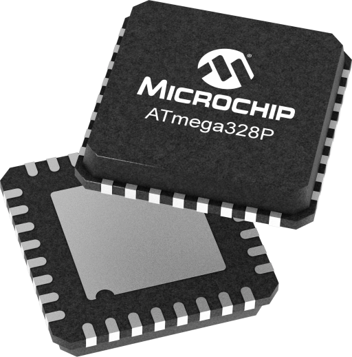 | ATMEGA328P-AU | Microchip | 3,520 | |
| ATMEGA328P-AUR | Microchip | 3,050 | |
 | ATMEGA328P-AURA0 | Microchip | 5,890 |
No. Start with the event that must be recognized and the functions required during the idle period. Reject any candidate mode that fails those requirements, then compare complete-cycle energy and response time. A board that misses its required event has not achieved a useful power saving.
Use it to understand the measurement setup, not to assign a final-PCB result. Record the powered circuits and the measurement boundary. Repeating a test on the actual board is necessary to distinguish MCU behavior from regulators, indicators, interfaces and attached equipment.
Microchip lists the same TQFP pin count and temperature range, with a different shipping format. Packaging does not define an application’s sleep policy. Keep the exact order code in procurement records and verify the actual device, board and programmed configuration during qualification. This is not a blanket replacement approval.
ATMEGA328P-AU is Microchip’s 32-pin TQFP AVR microcontroller with 32 KB of Flash and several sleep modes for balancing retained functions against power consumption. For an existing sensor or controller board, a useful sleep design starts with the event that must wake it. This guide connects mode selection, interrupt handling and board-level validation, without treating a datasheet current figure as a battery-life prediction.
By Beebee Chiang | YG Group
Use the ATmega328P documentation and the AU ordering entry when reviewing this board. Microchip’s product ordering table identifies ATMEGA328P-AU as a 32-pin TQFP part with a -40°C to +85°C range and tray packaging. The adjacent ATMEGA328P-AUR entry uses tape-and-reel packaging. These codes are useful procurement distinctions; neither should be confused with an automotive ordering code or the separate ATmega328PB device.
As checked on September 21, 2026, the same official product page marks ATmega328P not recommended for new designs. This guide therefore concentrates on understanding and improving an existing implementation. That status is not a statement that a particular lot is unavailable, nor does it decide whether replacing an established controller is economical. A new-platform decision needs its own support-horizon and migration review.
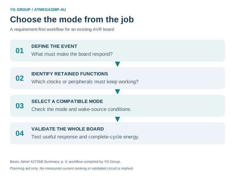
*Figure 1. A proposed mode-selection workflow for ATMEGA328P-AU. Start with the event and retained function, then validate the candidate mode. Based on the manufacturer’s [mode descriptions, p.4](https://5.imimg.com/data5/SELLER/Doc/2024/3/401171745/FR/JI/LH/3266212/atmega328p-u-th-microcontroller.pdf); the workflow is an engineering planning aid, not a measured power ranking.* *Figure 2. Control-flow illustration of the [AVR Libc protected sleep-entry pattern](https://onlinedocs.microchip.com/oxy/GUID-317042D4-BCCE-4065-BB05-AC4312DBC2C4-en-US-2/GUID-0EC704BC-648F-4BF6-90AE-0FAF9C596013.html). The diagram assumes a foreground loop that will re-enable interrupts; it does not configure a wake source, implement an interrupt handler or show elapsed time. The pending-work branch skips sleep.*Treat that as a deliberate design choice. The AVR Libc documentation describes a timed BOD-disable sequence for devices that support it, rather than a universal setting. Establish the selected device and mode’s behavior, the power-supply conditions and the required recovery behavior before using it. This guide does not supply a fuse change or a BOD-off recommendation.
Work through three separate records: whether the stimulus meets the configured recognition conditions, whether firmware preserves pending work across sleep entry, and whether the application completes its response in time. Capture each stage independently. Changing modes repeatedly without those observations can move the symptom without identifying its cause.
Before changing firmware, preserve the current board revision, clock source, fuse settings, compiler version and a known working binary. Photographing the board or recording the visible part marking is useful, but neither substitutes for its controlled bill of materials. A power comparison becomes difficult to interpret if the clock configuration and hardware change at the same time.
The question to settle first is what the board must continue doing while the CPU is stopped. A periodic sensing task, a conversion in progress and a controller waiting for a button are different requirements. Write the requirement before choosing the mode.
| Sleep mode | Documented functional distinction | Question for the design review |
|---|---|---|
| Idle | CPU stops; timers, SPI and interrupt logic can continue | Which ongoing peripheral activity prevents deeper sleep? |
| ADC Noise Reduction | ADC and asynchronous timer remain operating while CPU activity stops | Is the measurement interval the reason for sleeping? |
| Power-down | Oscillator stops; register contents are retained | Has the required wake event been qualified for this mode? |
| Power-save | Asynchronous timer continues | Does periodic scheduling require an independent time base? |
| Standby | Crystal/resonator oscillator remains running | Does retaining this oscillator help meet the response budget? |
| Extended Standby | Main oscillator and asynchronous timer remain running | Are both retained functions needed? |
Source: Atmel’s ATmega328/P Datasheet Summary, 42735B, November 2016, pp.2–4, manufacturer-authored document hosted by IndiaMART. The last column is an editorial decision aid. This is a functional overview, not an exhaustive wake-source or current table; peripheral configuration and the applicable device documentation still determine implementation details.
For a proposed periodic sensor application, define the interval tolerance and allowed response delay separately. “Measure occasionally” does not say whether the schedule may drift or whether an external event must receive an immediate response. Those two requirements can lead to different clock and wake arrangements. Treat the sensor application here as a design example, not a claim about a particular customer product.
A wake contract is a short record linking a real event to an observable result. It helps the schematic reviewer, firmware author and test engineer discuss the same behavior.
For each required event, record the following:
| Record | What to specify | Evidence to retain |
|---|---|---|
| Event origin | Button, external controller, timer or another defined source | Schematic net or peripheral configuration |
| Recognition | Input polarity or transition, interrupt route and enable state | Applicable device section and configuration dump |
| Event duration | Shortest pulse or longest permitted response delay | Interface requirement and captured waveform |
| Pending work | How software remembers that service is required | Queue or flag ownership and update rules |
| Completion | Observable action after wake | Test point, state update or response message |
This is a proposed review record, not a list of wake sources guaranteed in every mode. A pin’s alternate-function label alone does not establish its behavior when a clock has stopped. Equally, a successful interrupt test while the processor is running does not prove that the same stimulus will wake the sleeping system.
Keep one test for each event rather than relying on a combined demonstration. If a board wakes correctly when both a timer and a button are enabled, it can conceal a broken button path. Repeat the button test with unrelated wake events controlled, then check the combined behavior. Record unexpected returns from sleep as well as missed events: both can invalidate an energy budget.
The application can lose responsiveness even when the selected hardware mode is correct. One vulnerable pattern is checking that no work is pending, allowing an interrupt to change that condition, and then entering sleep anyway.
Microchip’s AVR Libc sleep documentation separates mode selection, sleep enable, the sleep instruction and sleep disable. Its test-and-sleep pattern checks the condition with interrupts disabled, enables sleep, then places sei() immediately before sleep_cpu(). The AVR execution rule documented there protects the instruction directly following SEI; after waking, the example clears sleep enable. Adapt this pattern to the actual foreground loop and interrupt ownership rather than inserting unrelated operations between those two calls.

Review the application’s work flag as carefully as the sleep calls. If an interrupt can update a variable, its visibility and access rules must match the compiler and data type. If two events can arrive before processing completes, decide whether a one-bit flag is sufficient or whether counting or queuing is necessary. A sleep-entry pattern cannot recover events that the application’s own bookkeeping discards.
There is also a practical test distinction: a board can return from sleep yet still fail its job. Confirm the requested operation completes, not merely that an interrupt service routine was entered. Use a visible state change or captured response appropriate to the application. Remove or account for that instrumentation when measuring power.
A useful response budget includes event recognition, clock recovery where needed, interrupt handling and the application’s work. A quoted processor wake number is only one possible contribution.
The Microchip clock clarification for ATmega328P explicitly separates oscillator start-up from the additional delay associated with reset. For example, its low-power crystal table lists 16K clock cycles for the crystal-oscillator start-up entries. The reset-delay column is a separate quantity with its own supply and fuse conditions. Do not copy either column into a universal event-to-response guarantee.
Build a timing worksheet with one row for each required event. Include the selected clock option, relevant fuse values, the point where the event is applied and the point where the required result is observed. For an external controller, agree when it may send meaningful data after requesting attention. For a sensor, agree whether settling and conversion happen before or after the response deadline.
Then test the cases that can expose timing assumptions: the shortest valid input event, closely spaced requests, the longest intended idle interval and the operating supply extremes of the actual design. These are suggested qualification cases, not results from testing an ATMEGA328P-AU board for this article.
Compare candidate firmware over a representative work cycle, with the same hardware, workload and measurement boundary. A lower reading during a quiet interval can be outweighed by additional active time, repeated wake events or extra work after every wake.
Atmel’s AVR4013: picoPower Basics demonstrates this whole-application approach on ATmega88PA, using firmware changes such as disabling unused modules, changing clock operation and sleeping between tasks. Its numerical results belong to that demonstration. They are not ATMEGA328P-AU specifications or a prediction for another circuit.
For the target board, separate MCU consumption from the regulator, indicator LEDs, sensors, communication interface and any debug connection. Keep a written inventory of which circuits remain powered. If the measurement is made at the battery connector, label it as a board-level result; if it is made on the MCU supply branch, label that narrower boundary.
A simple accounting relationship is:
Average current = total charge consumed during the observation interval / interval duration.
Use consistent units and an interval that includes the intended events. This relationship is an accounting tool, not a measured result. Include startup and recovery activity in the observation rather than discarding them because they complicate a quiet-current comparison. Battery-life estimates additionally need the battery’s usable capacity under the real load and operating conditions.
A useful review package contains the power trace, firmware identifier, measured supply, event schedule, connected equipment and the change under comparison. If a later firmware build increases current, those records make it possible to reproduce the earlier baseline and isolate the regression.
For an existing ATMEGA328P-AU design, begin with a defined event and retained-function requirement. Document the corresponding configuration, protect entry into sleep, then measure both responsiveness and complete-cycle consumption. Keep the selected mode, evidence and test procedure together so the result remains understandable after a board or firmware revision.