
Scarlett Zhang



12 views

| Picture | Part Number | Manufacturer | Stock | Action |
|---|---|---|---|---|
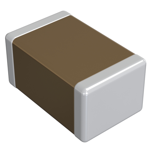 | GRM21BR61E106KA73K | Murata | 2,530 | |
| GRM21BR61E106KA73L | Murata | 5,350 |
No. The stated X5R temperature characteristic is tested under specified conditions, including no DC bias. It does not combine initial tolerance, applied DC voltage, AC-amplitude dependence, and aging into one ±15% limit.
The reviewed reference sheet does not supply an exact-part 12 V capacitance value. Obtain the corresponding characteristic data or measure it under defined conditions. The generic DC-bias example belongs to another capacitor and cannot supply that answer.
The reviewed document groups both under the same base capacitor specification and distinguishes their reel packaging. That supports considering a packaging substitution, subject to the actual BOM and assembly requirements. It is not an approval for unrelated parts with similar headline ratings.
It can help establish an initial baseline if the measurement conditions match the specification. It does not replace biased, temperature-dependent, and assembled-circuit validation for the intended application.
Murata GRM21BR61E106KA73K is a 10 µF, 25 V, X5R multilayer ceramic capacitor in an 0805 package. Its nominal capacitance does not establish the capacitance available on a powered rail. Selection requires checking DC bias, temperature, signal amplitude, aging, and the circuit's minimum capacitance requirement. The final K identifies reel packaging; it does not improve electrical performance or remove the need to verify effective capacitance.
For a decoupling or filtering design, the useful question is how much capacitance remains at the point of use. A purchasing description such as “10 µF ceramic, 25 V” cannot answer that question, even when the dielectric and case size are also correct.
Murata's GRM21BR61E106KA73-01A reference sheet identifies the following baseline. The cited document is dated June 25, 2026; its packaging table explicitly covers the K and L ordering variants. Murata reference sheet, pp. 2–3
| Item | GRM21BR61E106KA73K |
|---|
| Selection consequence |
|---|
| Nominal capacitance | 10 µF | Establishes the specified measurement baseline |
| Initial tolerance | ±10% | Is not a combined allowance for bias, temperature, and aging |
| Rated DC voltage | 25 V | Sets a voltage limit, not a capacitance-retention guarantee |
| Temperature characteristic | X5R; ±15% over −55°C to +85°C relative to 25°C under the stated no-bias test | Does not describe combined DC-bias and temperature behavior |
| Body dimensions | 2.0 × 1.25 × 1.25 mm, each ±0.15 mm | Check height as well as the nominal 0805 footprint |
| Final K packaging | 330 mm plastic-tape reel, 10,000 pieces | Confirm feeder and order-quantity requirements |
The specified room-temperature capacitance measurement uses 1.0 ±0.1 kHz and 1.0 ±0.2 Vrms. A bench measurement at a different frequency or amplitude is therefore a different test. That does not make the measurement useless, but it changes what can be concluded from it.
For incoming inspection, use the specified conditions and the applicable conditioning procedure. For circuit validation, also measure or model the part at the actual operating conditions. Keeping those two records separate prevents a common argument: a component can meet its nominal capacitance test while delivering less capacitance in a biased circuit.
For this article, effective capacitance means the capacitance relevant to a defined operating point: applied DC voltage, temperature, AC amplitude, frequency, and aging state. It is not a second fixed nameplate value.
Murata identifies voltage dependence, temperature dependence, AC-amplitude dependence, and aging as characteristics that must be considered for high-dielectric-constant capacitors. The reference sheet also warns that capacitance can change substantially as DC voltage rises, including below the rated voltage. These effects make the operating point part of the component specification used by the circuit designer. Murata reference sheet, pp. 11–13 and 32
It is useful to express the design requirement as:
Minimum qualified effective capacitance at the circuit conditions ≥ circuit-required capacitance.
The word “qualified” matters. A typical curve can support an estimate, but it may not establish a production minimum. A capacitance figure without its voltage, temperature, and measurement conditions cannot be used as a dependable lower bound.
Avoid multiplying a collection of unrelated percentages and calling the result a guaranteed worst case. A temperature curve measured with no DC bias and a room-temperature bias curve do not automatically describe their combined behavior. If the manufacturer supplies a model with defined applicability, follow that model. Otherwise, use the curves as planning evidence and validate the combined operating corners with suitable samples and margin.
The reference sheet's illustrative DC-bias plot is labeled for an X7R 0.1 µF, 50 V example. Its AC-amplitude example and temperature examples also identify other capacitance and voltage combinations. They explain mechanisms; they do not specify the bias curve of GRM21BR61E106KA73K.
Consequently, this article does not claim that the selected 10 µF part retains a particular percentage at 5 V, 12 V, or 24 V. That percentage would require exact-part characteristic data with its conditions, or a documented measurement. Reading a percentage from the generic plot and attaching it to this ordering code would create false precision.
For an approval package, request the exact GRM21BR61E106KA73 characteristics from Murata's product resources and preserve the downloaded data, date, curve conditions, and model version. Check whether a supplied plot is typical information or a guaranteed limit. Use that distinction when setting production acceptance criteria.
Before choosing how many capacitors to fit, write down the circuit requirement independently of the candidate part. For a regulator output, that includes the regulator's capacitance and ESR requirements across its operating range. For a local load, it includes the allowed voltage excursion and the part of the transient that must be supplied locally. For a filter, include the frequency range and the source and load impedances.
An illustrative charge-balance calculation shows why the distinction matters. Assume a local capacitor bank must provide an extra 0.1 A for 2 µs, and allocate 40 mV of droop to capacitance alone:
C_required = ΔI × Δt / ΔV = 0.1 A × 2 µs / 0.040 V = 5 µF
This is an idealized requirement calculation, not a measurement of GRM21BR61E106KA73K. It excludes ESR drop, connection inductance, the load-step edge, and the regulator's dynamic response. Those need their own voltage budget or a more complete simulation and measurement.
A 10 µF marking appears to offer twice the calculated requirement. That apparent margin is not yet established. The design still needs a supported minimum effective capacitance at the selected voltage and temperature. Initial tolerance alone can take the room-temperature nominal-test value down to 9 µF; it says nothing by itself about the remaining DC-bias reduction.
Use the following decision sequence:
If the capacitor bank falls short, the remedy may be another capacitor in parallel, a different case size, a different dielectric construction, or a changed circuit requirement. A higher voltage rating alone is not a universal guarantee of better capacitance retention. Compare the exact alternatives at the same application conditions.

An acceptable effective capacitance does not establish acceptable high-frequency behavior. The component's impedance, ESR, ESL, mounting geometry, and the return path all affect the assembled network. The voltage observed at a load can be dominated by the connection inductance during a fast edge even if enough stored charge is available for the later part of the transient.
Separate these questions during validation. First establish the capacitance available under bias for the slower charge demand. Then examine impedance and the installed current loop over the frequencies that matter. A nominal-capacitance comparison cannot stand in for both checks.
For filtering, also evaluate whether capacitance variation shifts the response beyond the required range. X5R is a useful classification for screening temperature behavior, but it is not a precision time-constant specification under arbitrary electrical conditions. A filter whose cutoff must remain tightly controlled needs an error budget that includes the capacitor's application-dependent variation.
The same care applies to multiple values placed in parallel. Adding another value changes the complete impedance network. Validate the assembled response rather than assuming that more nominal microfarads improve every frequency band.
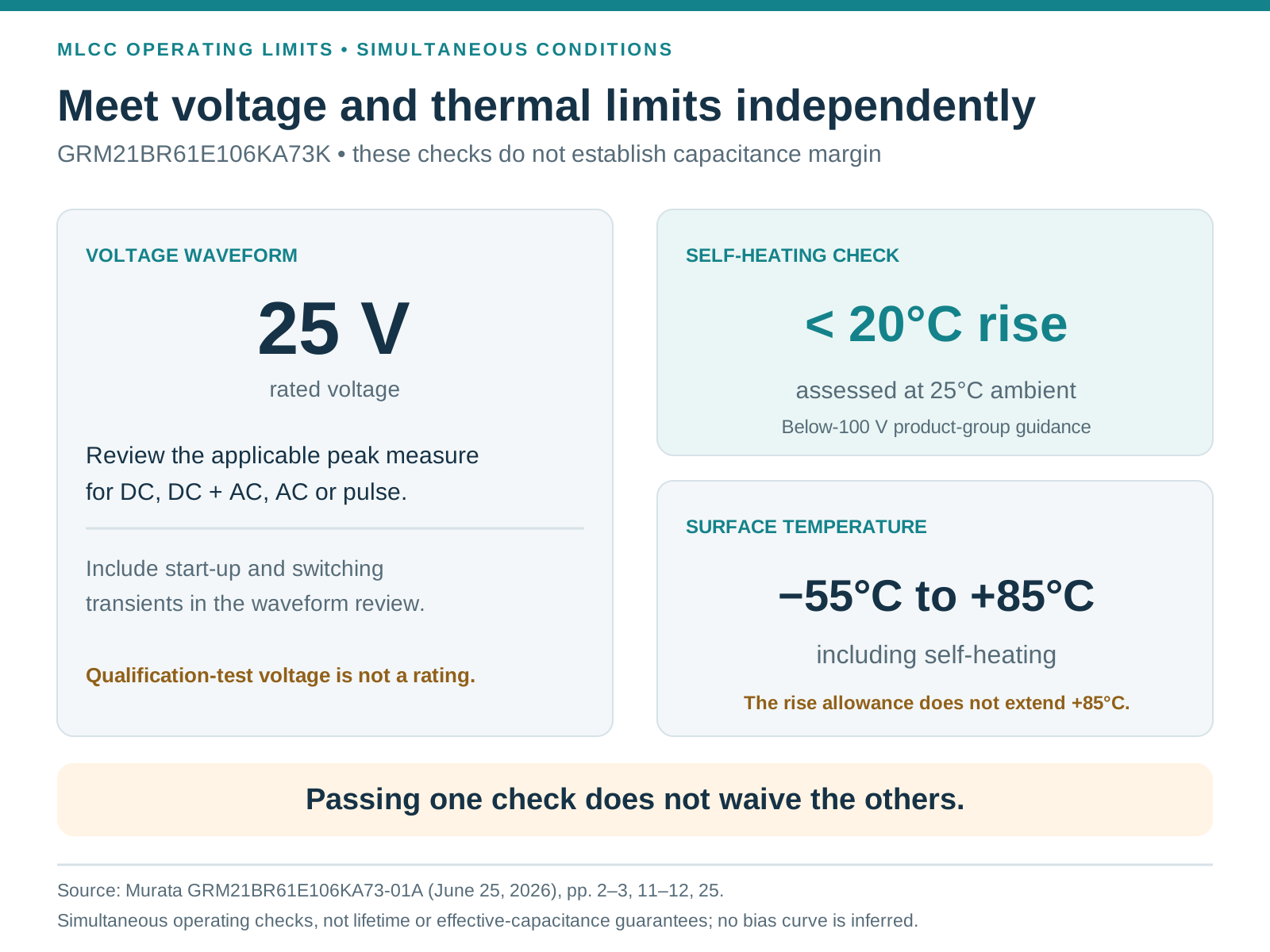
The 25 V rating should be checked against the actual waveform. Murata distinguishes DC, DC with superimposed AC, AC, and pulse excitation, and requires the applicable peak voltage measure to stay within the rated limit. Include start-up and switching transients when reviewing the waveform; a nominal rail label is not the maximum voltage seen by the capacitor. Murata reference sheet, pp. 3 and 11–12
A circuit can satisfy that voltage rule and still lack effective capacitance. Conversely, sufficient measured capacitance does not permit operation above the rated voltage. Treat the two requirements as separate pass conditions.
Ripple current also creates heat. For the below-100 V product group, Murata calls for self-heating below 20°C when assessed at 25°C ambient, while the capacitor surface temperature, including self-heating, must remain within its operating-temperature limit. These are simultaneous considerations; the self-heating allowance does not extend the +85°C operating limit.
The endurance and voltage-proof tests in the specification use their own elevated voltages and defined durations. They are qualification tests, not permission to operate a 25 V part continuously at those test voltages. Similarly, the reference sheet's estimated-useful-life charts are conditional reference information, explicitly not lifetime guarantees.
An electrically suitable ceramic capacitor can be damaged by board flex or thermal stress. Murata identifies solder volume, board separation, connector insertion, screw tightening, and test-probe loading as relevant causes of cracking. Cracks can reduce insulation resistance and lead to a short, so these are functional reliability concerns, not merely cosmetic defects. Murata reference sheet, pp. 14–22 and 26–32
Use the recommended land-pattern guidance for the actual component dimensions and soldering process, and validate it on the intended PCB. Do not substitute the specification's mechanical-test fixture dimensions for a production footprint without checking their purpose. Avoid excessive solder, provide support around probe and connector loads, and consider strain during board separation.
For a BOM release, preserve the complete ordering code. GRM21BR61E106KA73L is the closely related packaging option in the same reference sheet:
| Ordering code | Shared specified capacitor identity | Packaging difference |
|---|---|---|
| GRM21BR61E106KA73K | GRM21BR61E106KA73, 10 µF, 25 V, X5R | 330 mm reel; 10,000 pieces |
| GRM21BR61E106KA73L | Same base identity in this document | 180 mm reel; 3,000 pieces |
This supports a packaging comparison. It does not establish availability, pricing, interchange approval in a controlled BOM, or equivalence to a different manufacturer's “10 µF 25 V 0805” part. A packaging change still needs order-system, feeder, labeling, and traceability checks.
The reference sheet distinguishes the capacitor-tolerance K within the base number from the final packaging character. Preserve both positions when normalizing purchasing data. Removing the last character indiscriminately can hide a reel requirement; misreading it as a tolerance change creates a different kind of error.
GRM21BR61E106KA73K becomes a defensible choice when the record connects the exact part to the rail conditions, required capacitance, supporting characteristics, and PCB results. Keep nominal-test compliance, effective-capacitance margin, voltage stress, and assembly reliability as distinct checks. That gives both engineering and procurement a specification they can use without turning a 10 µF label into an unsupported in-circuit promise.
By Scarlett Zhang