
Ying Lin




| Picture | Part Number | Manufacturer | Stock | Action |
|---|---|---|---|---|
 | TPS54618CQRTERQ1 | Texas Instruments | 7,320 | |
 | TPS62816QWRWYRQ1 | Texas Instruments | 1,560 | |
| TPS62813QWRWYRQ1 | Texas Instruments | 4,900 | |
| TPS54618RTER | Texas Instruments | 5,580 | |
 | TPS53513RVER | Texas Instruments | 4,210 |
No. TPS54618CQRTERQ1 is an automotive ordering code, and TI's datasheet states AEC-Q100 Grade 1 qualification. That identifies the component specification. A particular shipment still needs traceable transaction, labelling and handling evidence. The suffix alone cannot establish its origin or condition.
The supplied SLVSEW2A title and electrical table use 2.95 V, while recommended operating conditions specify 3 V. Use 3–6 V as the conservative design-review baseline. A design that depends on the lower corner should resolve the discrepancy with TI rather than treating the headline as the only controlling statement.
TI identifies TPS54618CQRTERQ1 as a 16-pin RTE WQFN with a nominal 3 mm × 3 mm body and exposed thermal pad. Compare the controlled drawing and recommended land pattern with the approved board; a generic 16-pin QFN description is insufficient.
Category: ComponentSourcing
Author: Ying Lin
TPS54618CQRTERQ1 is Texas Instruments' automotive ordering code for a 6-A synchronous buck converter in a 16-pin WQFN package. A useful procurement review connects that complete code to the electrical specification, automotive qualification, package drawing and shipment records. The Q1 suffix helps identify the intended product class, but it cannot establish the origin or condition of a particular reel. Release the order only when those separate records agree.
A purchase request that says “TPS54618, automotive, 6 A” leaves several decisions unresolved. It does not distinguish TPS54618C-Q1 from the catalog TPS54618, identify the package carrier, or establish which qualification record the supplier intends to provide. Those omissions become expensive when purchasing, engineering and incoming inspection each fill in a different assumption.
TI's exact ordering page identifies TPS54618CQRTERQ1 as the automotive part, with RTE package code, 16 pins and an operating ambient range of −40°C to +125°C. The package option addendum in the supplied datasheet repeats the full ordering code and lists a nominal 3,000-piece large tape-and-reel carrier. That gives the buyer a traceable starting point. The datasheet family name and the purchase-order code are related identifiers, but they are not interchangeable fields. TI ordering information.
No. TI indicates that supporting documentation is available for functional-safety system design. The system team remains responsible for requirements, analysis, diagnostics and validation. A component designation does not establish the completed ECU's compliance or safety integrity.
It is a close catalog relative, not an approved automotive substitute in this article. TI classifies TPS54618RTER as Catalog. Qualification, electrical details, handling and application approval must be reviewed independently before any change is released.
Capture the full code, carrier, lot references, packaging condition and moisture-related label information. The supplied addendum lists Level-3-260C-168 HR and directs users to the shipping label for actual reflow information. Opened or repacked material needs disposition under the purchaser's controlled procedure.
For a hypothetical instrument-cluster board, the application description might be “a downstream logic rail supplied from a regulated low-voltage bus.” That wording matters. This is a converter with a 6-V operating ceiling, not a device to connect directly to an unconditioned automotive battery. A buyer should not interpret “automotive” as an electrical interface specification. Engineering must define the upstream rail, its tolerance and its transients before purchasing can approve a technically equivalent offer.
The manufacturer's applications include head units, instrument clusters and ADAS cameras. They support the relevance of this device class to vehicle electronics; they do not prove that a named vehicle or customer uses the part. A procurement article can still be practical without inventing an application history. Here, the example board is a design scenario for organizing the required evidence.
Table 1: Identity fields that should travel with the purchase request
| Field | TPS54618CQRTERQ1 evidence | Procurement consequence |
|---|---|---|
| Manufacturer and device | Texas Instruments; TPS54618C-Q1 | Preserve the C and Q1 identifiers in the approved device record |
| Complete ordering code | TPS54618CQRTERQ1 | Match the quote, order acknowledgement and reel label |
| Package | RTE, 16-pin WQFN, nominal 3 mm × 3 mm body | Compare the official drawing with the approved PCB footprint |
| Temperature qualification | AEC-Q100 Grade 1; −40°C to +125°C ambient | Match the program requirement; do not substitute junction temperature |
| Standard carrier | 3,000 units, large tape and reel | Confirm actual ordered quantity, carrier and lot handling |
| Marking and moisture data | 618CQ; Level-3-260C-168 HR in the addendum | Use the shipping label and applicable handling procedure for the actual shipment |
Source: TI datasheet SLVSEW2A, pages 1, 37–43, and the exact ordering page. Compiled by YG GROUP. Package and carrier values identify the catalog configuration, not the contents of an unexamined shipment.
The last distinction is easy to overlook. A data table can establish what TI offers. It cannot establish that a reel supplied through a particular transaction contains that product, was stored appropriately, or has an intact chain of custody. The release packet should therefore contain two linked records: the approved component definition and the evidence for the delivered material. Keeping them separate makes gaps visible without treating every missing commercial document as a silicon design defect.
The datasheet states AEC-Q100 qualification and Grade 1 ambient temperature coverage. That is useful evidence for choosing an automotive component. It belongs in the approved component record with the document revision and the date it was checked. It should not be reduced to a handwritten “auto grade” note, because the temperature grade and exact device association may matter during an audit or an engineering change.
Qualification, however, is a product and process evidence question. Authentication is a transaction question. A counterfeit device could carry a convincing suffix or top marking; conversely, a legitimate shipment might require clarification because its label uses an additional internal ordering identifier. Neither situation is resolved by repeating the first page of the datasheet. The correct action is to reconcile the manufacturer's documented identity with the supplier's shipment records.
TI also labels the product Functional Safety-Capable and indicates that documentation is available to assist functional-safety system design. That designation does not certify the completed ECU or establish an ASIL result for the application. The system team still has to determine the relevant safety requirements, failure effects and diagnostic coverage. Purchasing can ensure that the requested device and supporting records are available; it cannot turn a component capability label into a system-level compliance conclusion. TI product and ordering page.
A sensible document request identifies the exact part, the manufacturing information needed by the project, and the required relationship to the shipped lot. Asking only for “a quality certificate” invites a generic response that may say very little about the material being purchased. Ask instead what the document covers, who issued it, which code it names and whether it refers to the actual shipment or to the general product family.
The TI ordering page exposes a quality, reliability and packaging information entry. Its listed scope includes material content, moisture sensitivity, device marking, qualification summaries and reliability information. Access to that entry is a route for gathering evidence; its existence is not proof that every report has already been downloaded and accepted. When a report cannot be retrieved, leave that evidence item open and assign an owner to obtain it. Do not quietly replace a missing qualification summary with a distributor's product description.
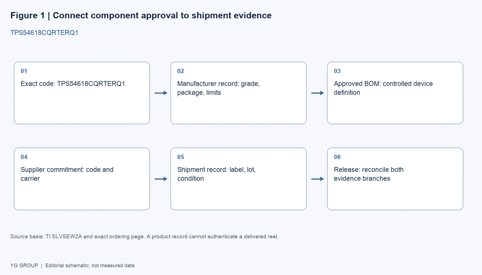
Figure 1: Two evidence branches for TPS54618CQRTERQ1 procurement. The manufacturer branch defines the approved component; the shipment branch establishes what is being delivered. This is an editorial workflow schematic, based on the fields exposed by TI's ordering and packaging documentation, not an authentication test. Diagram: YG GROUP.
The diagram deliberately rejoins the branches at release. Engineering can approve a device while purchasing still has an unresolved supplier document. Incoming inspection can confirm a label while engineering has not approved a substituted package. A single green status hides these differences. Two explicit decisions, followed by one release decision, preserve responsibility and make handover easier when staff or suppliers change.
The RTE package has an exposed thermal pad. The TI drawing states that it must be soldered to the board for thermal and mechanical performance, and the layout section connects the ground and analog-ground arrangement to the thermal pad and ground planes. This means package verification cannot stop at “16-pin QFN.” Body size, pitch, exposed-pad geometry, land pattern, solder mask and assembly process all affect whether the accepted component can be built reliably.
For an existing production board, compare the controlled footprint revision against the actual package drawing supplied with the approved datasheet. The drawing is more useful than a generic distributor package icon. Generic pictures can represent a package family; the controlled dimensions and notes determine the engineering interface. Where a supplier proposes an apparently similar regulator, require a separate package comparison instead of relying on the matching number of leads.
The moisture sensitivity entry is also a handling condition, not an indication of electrical quality. The supplied addendum lists Level-3-260C-168 HR and notes that the shipping label should be consulted for the actual reflow information. The receiving process should capture the label, packaging condition and applicable exposure history before material reaches assembly. A buyer should involve manufacturing quality when a reel has been opened, repacked or split, because the necessary disposition depends on the actual evidence and the site's controlled procedure.
A full reel and a cut-tape order can both be legitimate commercial formats. The question is whether the agreed format preserves the information needed for the job. For engineering samples, a smaller quantity may be entirely suitable. For a regulated production program, the supplier's approach to reel splitting, lot segregation and labelling may need explicit acceptance. Do not infer the actual carrier from the final R in the ordering string when the transaction includes a separate custom-reel service.
TI explains that custom reels can join cut tape with leaders and trailers and that cut-tape fulfillment can involve multiple strips. That is a reason to ask how lots will be represented, not a reason to classify every non-full-reel shipment as defective. The purchase order should describe acceptable packaging and lot documentation in language the receiving team can check. TI carrier explanation.
Table 2: Records for a practical release packet
| Record | What it should answer | Owner or reviewer | What it does not establish alone |
|---|---|---|---|
| Approved BOM entry | Is the full code and manufacturer correct? | Component engineering | Actual shipment origin |
| Datasheet and package drawing | Does the board meet the specified interface and limits? | Hardware engineering | Lot traceability |
| Qualification information | Which product, grade and process evidence apply? | Quality engineering | System safety certification |
| Supplier quotation and acknowledgement | What exact material and packaging are committed? | Purchasing | Electrical suitability |
| Shipment label and transaction documents | Which quantity, lot references and carrier arrived? | Receiving and quality | Complete device authenticity |
| Change-notification review | Has an applicable change been evaluated? | Component engineering and quality | Future availability or price |
Source: editorial release workflow derived from TI's ordering, qualification-information and packaging fields. Compiled by YG GROUP. Ownership should be adapted to the purchaser's quality system.
A procurement reviewer does not need to redesign the converter. The reviewer does need to preserve the distinctions that determine whether an alternative quote changes the engineering requirement. For this device, those distinctions include operating input voltage, ambient versus junction temperature, continuous output current versus current limit, and typical efficiency versus guaranteed electrical limits.
The supplied SLVSEW2A document contains a small but meaningful input-voltage inconsistency. Its title and electrical-characteristics table describe operation from 2.95 V, while Section 6.3 lists a recommended input range beginning at 3 V. A robust procurement record should retain that difference. Use 3–6 V as the conservative operating-design baseline unless the engineering team has resolved a required 2.95-V corner with TI. A marketing header should not silently overrule the recommended-operating-conditions table.
The same document lists 7 V as an absolute maximum for VIN. That is a stress boundary, not an acceptable nominal input. If a proposed upstream supply can exceed the operating ceiling during tolerance, start-up or a transient, the problem belongs in the electrical review. Ordering an automotive-qualified version does not remove it. Similarly, thermal shutdown is a protective behavior; it is not the target operating temperature for a regulator expected to deliver a controlled lifetime.
The headline 6-A capability is a continuous-output design capability, subject to the complete circuit and thermal conditions. It is different from the switch-current-limit values, which include tolerance and operating conditions. Selecting the inductor solely for 6 A can be inadequate during start-up or overload. TI's design section explicitly discusses ripple, peak current, saturation and the possibility of approaching the switch current limit. These details explain why a procurement substitution can force a review of the surrounding bill of materials.
Table 3: Parameters whose context must remain in the approved record
| Item | Evidence in SLVSEW2A | Interpretation for review |
|---|---|---|
| Input operating range | Title and Section 6.5: 2.95–6 V; Section 6.3: 3–6 V | Resolve the lower-edge discrepancy if the design depends on it |
| VIN absolute maximum | 7 V | Stress limit; not a permitted continuous operating target |
| Ambient range | −40°C to +125°C | Qualification and operating context; not interchangeable with junction temperature |
| Output capability | Up to 6 A continuous | Requires suitable thermal design and external components |
| Clock synchronization | 300 kHz to 2 MHz | Keep separate from the resistor-mode timing table |
| Thermal-pad connection | Pad soldering and ground-plane connection required | Footprint and assembly changes affect thermal performance |
Source: TI SLVSEW2A, Sections 5–7 and 10. Compiled by YG GROUP. This table selects procurement-relevant boundaries; it does not replace the complete electrical specification.
A nominally similar converter can regulate the same output voltage and still require different compensation, switching frequency, inductance or sequencing. TPS54618C-Q1 uses peak current-mode control with an external compensation network. Its soft-start/tracking and power-good pins also participate in multi-rail start-up. Those are part of the approved implementation, even when the purchasing description mentions only voltage and current.
Output capacitance is another hidden link. TI's application example considers transient response, ripple, capacitor ESR and capacitance loss from bias, temperature and ageing. Changing the converter may change those requirements; changing the capacitor supplier may change the effective capacitance even when the printed capacitance is unchanged. The sensible rule is to identify which controlled BOM items are coupled to the regulator approval and route changes through the same engineering owner.
An alternatives list becomes useful when it explains why a device deserves investigation and what prevents immediate release. The four parts below are real TI orderable products selected for different comparison purposes. They are not four interchangeable ways to purchase the main device. Two preserve automotive positioning while changing implementation, one is a close catalog relative, and one shows how a broader power specification can conceal a qualification and package mismatch.
Table 4: Four related orderable models and their decisive differences
| Model | Relevant relationship | Difference that changes the decision | Required review before use |
|---|---|---|---|
| TPS62816QWRWYRQ1 | Automotive 6-A buck-converter candidate | Nine-pin 2 mm × 3 mm package with wettable flanks and a different frequency range | Redesign footprint, external network, timing and thermal implementation |
| TPS62813QWRWYRQ1 | Automotive lower-current buck candidate | 3-A device in the nine-pin RWY package | Confirm load demand and redesign the implementation |
| TPS54618RTER | Close catalog 6-A relative | Catalog rating rather than the main part's automotive qualification record | Review qualification, handling, electrical details and approval scope |
| TPS53513RVER | Higher-current buck comparison | Catalog 8-A device, 28-pin RVE package and D-CAP3 control | Treat as a new design, including bias supply and control behavior |
Sources: TI exact ordering pages for TPS62816QWRWYRQ1, TPS62813QWRWYRQ1, TPS54618RTER and TPS53513RVER. Compiled by YG GROUP. None is established here as a drop-in replacement.
TPS62816QWRWYRQ1 deserves attention because TI itself points readers of TPS54618C-Q1 toward the newer device family. That recommendation identifies a design option. The different pin count alone makes clear that it is not permission to load the old PCB unchanged. Wettable flanks may be relevant to an assembly-inspection strategy, but their presence does not eliminate the need to qualify the new solder process and layout.
TPS62813QWRWYRQ1 asks a different question: does the load actually require the main device's current class? If the sustained and transient current budget fits a smaller device, a redesign may be worthwhile. A purchasing shortage does not answer that question. Engineering needs a verified load envelope, including start-up and fault recovery, before it can approve the reduced-current candidate.
TPS54618RTER is the most useful warning against judging by name similarity. It shares a familiar root and package designation, yet the official page classifies it as Catalog. A numerical temperature value in a distributor list should not be used to reconstruct the automotive qualification claim. The buyer should preserve both records and request an explicit component-engineering decision if anyone proposes crossing that boundary.
TPS53513RVER demonstrates the opposite trap: a larger current number and wider power-stage input range do not make a candidate universally safer. Its different control method, pin count and supply requirements change the implementation. A broader parametric search result is a starting point for engineering comparison, not an approved alternate on the purchase order.
Incoming inspection works best when each check has a limited, explicit purpose. A label review checks agreement with the order and supporting records. A dimensional inspection checks the package against a controlled drawing. A functional sample test checks behavior under defined electrical conditions. These checks complement one another, but a passing result from one cannot automatically close a failure in another. For example, a converter that produces the expected output on a bench has not thereby demonstrated the qualification history required by the automotive program.
The same discipline applies to top markings. The supplied packaging addendum lists 618CQ and explains that additional markings can relate to the logo, lot trace information or environmental category. This gives receiving a reference for investigation. It does not justify rejecting every additional character or accepting every device with those five characters. Where marking information conflicts with the label or source documents, capture the discrepancy and seek a manufacturer-supported explanation rather than improvising a decoding rule.
If the organization uses a functional incoming test, hardware engineering should define the fixture and acceptance criteria. For TPS54618CQRTERQ1 that includes the input supply, programmed output, load, compensation, switching-frequency setting and thermal conditions. A loose instruction to “test at 6 A” omits the conditions that determine regulator behavior. The device's exposed pad, input bypassing and short switching-current paths are essential parts of the fixture, not optional details to be added after a sample fails.
Start-up behavior also needs a defined initial condition. TI describes soft-start, tracking, undervoltage lockout and prebiased-output protection mechanisms. A fixture that powers the load or a signal pin before the regulator can produce a different sequence from the intended board. Record the sequence and relevant waveforms so a failed result can be reproduced. The goal is to distinguish a material issue from a fixture or application issue without using the test to claim capabilities it never examined.
Temperature evidence requires similar care. A brief room-temperature regulation check cannot validate operation across the automotive ambient range. Thermal-chamber testing, where required by the program, needs its own procedure and sample rationale. A case-temperature reading cannot simply be substituted for junction temperature, and the datasheet's thermal metrics depend on the stated board conditions. The appropriate result is a narrowly worded test record that says what was exercised and what passed.
Do not destroy the original association between material and records while investigating. Keep the relevant packaging, label images and transaction references linked to the affected quantity. If several lots arrived together, identify which observations belong to which lot. This is an organizational recommendation rather than a claim about any particular supplier, and it makes later technical discussion more precise.
For a replacement proposal, use a separate sample and approval record for the candidate. Running an alternative on a modified evaluation board may demonstrate a promising redesign, but it does not approve substitution on the existing production assembly. Record the modifications, the requirements that were rechecked and those still open. That distinction lets purchasing pursue options quickly while preserving the engineering meaning of the approved BOM.
The release packet should end with a decision a second person can reproduce. “Looks correct” is hard to transfer. “Full ordering code matches the approved BOM, package drawing matches footprint revision, quality documentation is linked, and shipment records are reconciled” is much more useful. Each statement identifies a check, an object and evidence that can be reopened later.
For the example cluster board, engineering first confirms the regulated input range and the thermal implementation. Quality then checks that the requested automotive evidence corresponds to the approved device. Purchasing confirms the supplier's commitment to the exact code and packaging. Receiving reconciles the delivered labels and documents with that commitment. If a mismatch appears, the material remains associated with its original evidence while the responsible team decides the disposition.
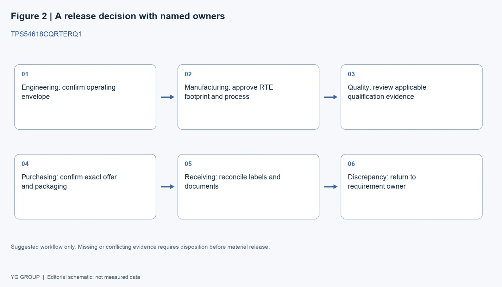
Figure 2: Suggested procurement release sequence for TPS54618CQRTERQ1. A discrepancy returns to the owner of the affected requirement; it does not disappear when another check passes. This is a process schematic, not a measured quality or failure-rate chart. Diagram: YG GROUP.
Suppose the quoted material includes an additional identifier that appears on TI's page as an identical ordering variant. That deserves a documented comparison to the manufacturer's explanation, not an automatic rejection based on a string difference. Conversely, removal of the C or Q1 portion should not be dismissed as a typographical shortening if it changes the named product. A discrepancy review should distinguish a supported alias from a different device.
A revision change deserves the same precision. Read the revision history and identify whether the change affects the approved application, package, qualification or only an editorial detail. Keep the document revision used for the design review and the current document used for procurement visible together. The date on a downloaded packaging addendum may differ from the core datasheet revision; record both instead of forcing them into one invented release date.
Table 5: Discrepancy handling before material release
| Finding | Immediate action | Evidence needed for closure |
|---|---|---|
| Shortened or altered part number | Obtain the exact proposed ordering code | Manufacturer mapping and approved BOM decision |
| Qualification report names a different family | Hold qualification acceptance | Applicable report or written manufacturer clarification |
| Package code differs from the approved design | Route to hardware and manufacturing engineering | Drawing comparison and approved implementation change |
| Opened or repacked moisture-sensitive material | Preserve condition and exposure records | Disposition under the site's controlled handling procedure |
| Operation relies on 2.95 V minimum input | Escalate the datasheet discrepancy | Engineering analysis and, when needed, TI clarification |
| Supplier asserts an immediate substitute | Remove automatic alternate status | Electrical, mechanical and qualification review for that candidate |
Source: YG GROUP editorial workflow, grounded in the distinctions in TI SLVSEW2A and the exact ordering records. It is a suggested review aid, not a replacement for a purchaser's approved quality procedure.
The procurement conclusion is straightforward: approve a defined component and a documented shipment, then connect the two. TPS54618CQRTERQ1 has an identifiable automotive grade, package and specification. The value of the review is in preserving those details through quotation, design approval and receiving, while making unresolved points visible before they become production assumptions.