
Jolin Zeng




| Picture | Part Number | Manufacturer | Stock | Action |
|---|---|---|---|---|
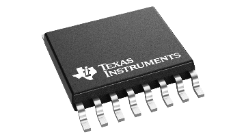 | TAS5431QPWPRQ1 | Texas Instruments | 8,820 | |
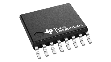 | TAS5411QPWPRQ1 | Texas Instruments | 7,700 | |
| TAS5421QPWPRQ1 | Texas Instruments | 6,410 | |
| TAS5441QPWPRQ1 | Texas Instruments | 7,920 | |
 | TAS6421QDKQRQ1 | Texas Instruments | 3,450 |
Open-load diagnosis is reported through I²C only; it does not assert FAULT. A controller that monitors only the discrete pin can miss this condition. Read the load-diagnostic register after a valid completed cycle.
Approximately 229ms describes the nominal sequence. The check phase can repeat and protection events can interrupt diagnostics. Use the reported state and a qualified system timeout rather than treating 229ms as an unconditional maximum.
The seven-bit address is 0x6C. The datasheet shows 0xD8 for write and 0xD9 for read when the direction bit is included. Use the convention required by the host API and verify the actual bus transaction.
No. Standby makes I²C inactive and resets registers. Non-blocking means the amplifier does not hold the shared bus low, allowing other devices to communicate; it does not mean TAS5431 remains addressable.
Category: Applications&Solutions
Author: Jolin Zeng
TAS5431QPWPRQ1 can help an eCall controller distinguish an open speaker circuit, a shorted load, and shorts from an output to supply or ground. Its usefulness depends on running and interpreting the load diagnostic sequence correctly. An open load is reported through I²C without asserting FAULT, and a normal electrical result does not prove that the complete acoustic or emergency-call path works. Build the system decision from diagnostic state, register results and independent audio-path validation.
Texas Instruments identifies TAS5431-Q1 as a mono automotive class-D amplifier with differential analog inputs. The term digital-audio amplifier in its datasheet title describes the switching power architecture; it does not make the audio input an I²S interface. Audio enters IN_P and IN_N through the specified coupling network. I²C configures the amplifier and returns status. Confusing those two interfaces can lead to an unsuitable selection before the diagnostic features are even considered.
The exact orderable TAS5431QPWPRQ1 uses the 16-pin PWP HTSSOP package with a downward-facing exposed thermal pad. The adopted datasheet is SLOSE43A, revised July 2020, with later packaging addenda. Its automotive qualification is AEC-Q100 Grade 1, covering an ambient range of −40°C to 125°C. That component qualification supports a component selection review; it does not certify a completed eCall implementation or its ability to communicate under every vehicle condition.
Table 1: Identity and operating conditions that frame the diagnosis
No. It means no supported electrical load fault was detected in that valid diagnostic cycle. The speaker, enclosure, signal path and complete emergency-call function require their own performance verification.
No. The headline point depends on supply voltage, load and distortion. Verify PVDD at the amplifier, available output, audio quality and runtime with the actual backup source and speaker.
| Item | Datasheet basis | Consequence for the controller design |
|---|---|---|
| Audio topology | Mono bridge-tied load, differential analog input | Both speaker conductors are active outputs |
| Exact package | PWP HTSSOP, 16 pins, thermal pad to ground | Use the actual pinout and thermal land |
| Recommended PVDD | 4.5–18 V with a 4 Ω ±20% or higher load | Check the lowest backup-supply voltage at the IC |
| Low-impedance condition | 5–18 V for a 2 Ω ±20% load | The 4.5 V minimum is not universal |
| Output-power example | 8 W at 10% THD+N, 4 Ω, 14.4 V supply | This is not the output available from every battery |
| Control and reporting | I²C plus STANDBY, MUTE and FAULT | Host firmware is needed for full fault classification |
| Ordering record | 2000-piece large tape and reel, −40°C to 125°C | Keep the complete code in the released BOM |
A speaker connection includes more than its nominal impedance. The load diagnostic sees the path through the output filter, PCB, connectors, harness and voice coil. Added resistance, leakage or capacitance in that path can change the result. Define where a test fault will be inserted and which portions of the harness remain connected. Otherwise two engineers may both report an open-load test while actually exercising different electrical networks.
The device is intended for a bridge-tied speaker. Neither OUTP nor OUTN is a speaker ground. A test fixture that grounds one conductor because it resembles the negative terminal of a single-ended amplifier can create the very fault being investigated. Differential measurement and a fixture designed for the two active outputs are therefore part of a meaningful diagnostic evaluation.
The load test starts when STANDBY is deasserted and also occurs in specified fault-recovery situations. During the test the output power stage is high impedance while the diagnostic circuitry applies a controlled DC bias. High impedance here does not mean that the output network is electrically untouched. The bias and its settling behavior are essential to the measurement, which is why output capacitance is constrained.
The nominal sequence contains a 75 ms discharge phase, a 52 ms ramp up, a 50 ms check and a 52 ms ramp down. Those intervals total approximately 229 ms. The check phase can repeat up to five times when a fault or a large output-to-ground capacitor is present. The approximately 229 ms figure is consequently a description of the ordinary sequence, not an unconditional maximum startup time for firmware to enforce.

Figure 1: The host must distinguish waking the amplifier, waiting for a valid diagnostic result and interpreting that result. The nominal diagnostic phases total about 229 ms; retries or protection events can extend or interrupt the sequence.
Table 2: Diagnostic timing and the decisions it allows
| Stage | Nominal duration or indication | Host interpretation |
|---|---|---|
| Exit standby | I²C becomes active approximately 1 ms after STANDBY goes high | Bus access can precede completion of the speaker test |
| Discharge | 75 ms | Previous output charge is being removed |
| Ramp up | 52 ms | The diagnostic bias is being established |
| Check | 50 ms, with possible repeated checks | Do not assume the first scheduled read is final |
| Ramp down | 52 ms | The diagnostic bias is being removed |
| Result evaluation | Status register identifies diagnostic and operating state | Associate fault bits with a completed, valid cycle |
The datasheet specifies that diagnostics run after every other overvoltage event. A controller should therefore avoid the blanket assumption that every supply disturbance produces one fresh, complete load measurement. Track the observed state and the event that caused the amplifier to leave normal playback. A recorded diagnostic result needs a cycle context if it is to support a useful service conclusion.
Overtemperature, overvoltage or undervoltage during the test can cause the device to exit diagnostics, potentially with a pop or click. Such an interrupted test should not be logged as a successful speaker check merely because the last byte read contained no load-fault bits. Firmware needs an explicit distinction between a completed test, a test still running, and a test whose operating conditions became invalid.
Choose a timeout from the system's permitted startup behavior and measured worst-case operation with the qualified network. Keep it separate from the nominal timing arithmetic. If the timeout expires, preserve that outcome as a timeout or unavailable result. Relabeling it as an open speaker would hide the difference between a load problem, excess settling time and a supply that never allowed the test to finish.
The three relevant register addresses have different jobs. Register 0x01 is a latched fault register, 0x02 reports current status and load diagnostics, and 0x03 controls gain, switching frequency and SpeakerGuard settings. Treating all three as interchangeable status bytes makes it difficult to distinguish what happened earlier from what the amplifier is doing now.
In register 0x02, D0 indicates an output short to PVDD, D1 a short to ground, D2 an open load and D3 a shorted load. D4 indicates a fault condition, D5 that diagnostics are running, D6 mute mode and D7 play mode. The resulting byte should be decoded by bit meaning, rather than compared only with a few complete-byte constants. State and fault information can otherwise be lost when the application encounters a combination that was absent from a simple bench demonstration.
The latched register records load-diagnostic fault occurrence at D2, overcurrent shutdown at D3, undervoltage at D4, overvoltage at D5, DC-offset protection at D6 and overtemperature shutdown at D7. Its two lowest bits are reserved. The supplied register table does not justify inventing a generic write-one-to-clear operation for this read-only register. Implement clearing and recovery only from documented behavior and verified device operation, preserving reserved-bit rules in the driver.
Table 3: Electrical result versus the system conclusion
| Observation | Device-level meaning | What it does not establish |
|---|---|---|
| Open-load bit | The tested load path meets the open-detection condition | Exact location of the break or acoustic output |
| Shorted-load bit | The load path meets the short-detection condition | Which wire, connector or speaker element caused it |
| Short-to-PVDD bit | An output-to-supply fault is detected | The root cause of the harness or board fault |
| Short-to-ground bit | An output-to-ground fault is detected | A complete insulation assessment of the vehicle wiring |
| Diagnostic-active bit | The measurement is in progress | A final pass or fail result |
| No load fault after a valid cycle | No supported electrical load fault was detected in that cycle | Voice intelligibility or end-to-end eCall readiness |
The open-load behavior deserves particular attention. The amplifier can continue operating after detecting an open circuit, and open load has I²C reporting only. It does not assert FAULT for that condition. A design that monitors only the discrete FAULT pin can therefore miss a disconnected speaker even though the amplifier has correctly detected it internally.
Other detected load faults hold the output in high impedance while the device continues checking for their removal. When the output condition becomes normal, audio can start. The host must decide how automatic recovery fits the system policy. It may need to retain the earlier fault for service records even after the electrical path recovers, especially when an intermittent connector becomes normal before a technician examines the vehicle.
The shorted-load threshold is specified from 0.9 Ω to 1.5 Ω, with 1.2 Ω typical, including the speaker wires. The open threshold spans 70 Ω to 120 Ω, with 95 Ω typical. These are detector thresholds under the electrical table's stated conditions, not a precision resistance measurement and not a guarantee that every unit switches at the typical value.
TI's threshold illustration explicitly includes transition regions. Between the minimum and maximum short threshold, the device may classify the path as normal or shorted. Between the minimum and maximum open threshold, it may classify the path as normal or open. A test plan that uses exactly 1.2 Ω or 95 Ω and demands one fixed answer from every board would confuse typical behavior with a guaranteed decision boundary.
For an illustrative nominal 4 Ω speaker, the DC resistance of the voice coil is not automatically 4 Ω. Nominal speaker impedance is an audio-frequency characteristic, while the diagnostic applies a DC-oriented test to the connected network. Obtain the speaker's actual resistance information, include harness and connector contributions, and validate the whole path over the required conditions. Do not insert nominal impedance into a threshold calculation as if it were a measured DC value.
A resistance substitution fixture can map detector behavior, but it should include the output filter and wiring that will be present in the product. Begin with values clearly inside the intended normal and fault regions, then examine boundary behavior separately. Record resistor tolerance, connection topology and supply voltage. This provides evidence about diagnostic classification without pretending that a resistor duplicates the acoustic and electromechanical behavior of the actual speaker.
The output-to-PVDD or ground short-detection row lists 200 Ω under its stated test conditions. That value is another diagnostic characteristic, not an allowed external fault current or a design target for protective components. The board's fault-insertion method must account for the active bridge outputs and the available supply energy. A diagnostic feature cannot make an arbitrary bench short or an unsuitable test fixture valid.
The recommended conditions limit external capacitance from each OUT_X pin to ground to 4 µF. The ordinary application shows 3.3 µF output-filter capacitors along with smaller EMI components. The capacitors are part of the electrical network that the diagnostic has to bias, so a filter change can affect both audio or EMI behavior and the time needed to classify the load.
Increasing a capacitor to improve emissions is therefore a cross-functional design change. Check its tolerance and the total capacitance seen by the output, not just the largest capacitor's nominal label. Include optional components, the qualified cable arrangement and any protection network that adds capacitance. Then repeat diagnostic startup and recovery testing as well as the intended emissions assessment.
An unexpectedly long diagnostic interval after a filter revision is a reason to inspect the changed output network. It is not by itself proof that the speaker has become intermittent. Compare the same load and supply with the previous and revised networks while observing diagnostic-active status. This comparison separates a settling effect from a real change in the connection being tested.
The power outputs require the specified low-pass filtering for the intended implementation. Bootstrap capacitors connect BSTP to OUTP and BSTN to OUTN, and the analog inputs need AC coupling. Those supporting circuits serve different purposes and should not be merged into a generic capacitor budget. In particular, the output-to-ground limit is not a license to move or omit bootstrap, BYP or supply-decoupling components.
The thermal pad must be soldered to ground. TI's layout guidance emphasizes top-layer copper, short output routes to the LC network, appropriate ground planes and thermal vias. A board that repeatedly reaches thermal protection can interrupt diagnosis or playback even with a healthy speaker. Correct interpretation therefore needs power-stage operating conditions as well as the load-fault bits.
The wide supply range supports evaluation for backup-battery operation, but it does not establish an eCall module's runtime or audio level. For a 4 Ω ±20% or higher load, the recommended minimum is 4.5 V at PVDD. A nominal battery voltage measured without load does not show that the amplifier remains inside this range during audio peaks, cold operation or a switchover transient.
The 8 W headline applies to a 14.4 V supply, 4 Ω load and 10% THD+N. The electrical table also lists a 6 W point at no more than 1% THD+N under its specified conditions. These points illustrate why a power claim needs both voltage and distortion. They do not provide a guaranteed output-power point at the lowest backup voltage, and no such point is inferred here.
Brownout affects control as well as sound. Below the power-on-reset threshold, the I²C interface becomes high impedance. Recovery restarts the device with default register settings. If firmware previously reduced gain or selected a SpeakerGuard limit, it needs a defined method to restore and verify that configuration following the reset. Otherwise the acoustic path after recovery may differ from the path tested before the voltage event.
STANDBY also resets registers and makes I²C inactive. The non-blocking feature means that the amplifier does not hold the shared I²C bus low in standby; it does not mean that its registers remain readable then. The host should distinguish a deliberately sleeping device from an active device that fails to acknowledge. That distinction prevents ordinary power management from generating misleading communication-fault records.
Supply decoupling and distribution belong in this review. The datasheet describes nearby 10 µF and 0.1 µF ceramic capacitors with a larger 330 µF bulk capacitor in its application. These values are a design example to evaluate, not evidence that any battery, cable and PCB combination will have acceptable droop. Measure PVDD at the amplifier while exercising the relevant audio and diagnostic transitions.
The fixed I²C address appears as 0xD8 for write and 0xD9 for read when the direction bit is included. The corresponding seven-bit address is 0x6C. Match the convention expected by the host driver. Supplying an already shifted address to a function that shifts internally is a common way to create an apparent device fault that is actually a software-interface mismatch.
Use separate software states for standby, waking, diagnostic activity, valid load result, playback and unavailable communication. Associate each saved result with the supply state and the most recent standby or reset transition. A stale normal result from the previous ignition cycle must not silently stand in for a new test that never completed.
MUTE is active high and stops output switching; STANDBY is active low and enters shutdown. Neither pin has an internal pullup or pulldown, so reset-time pin behavior must be designed. The datasheet directs MUTE low in standby. Firmware and external biasing should agree on these levels before the controller's GPIO configuration becomes active, including after a reset caused by the backup supply.
Do not present a production-ready register script without knowing the system's intended gain, power limit and startup policy. A reviewable driver design instead states which configuration is expected, when it is written, how readback is checked, and which events invalidate it. Preserve raw register bytes alongside decoded labels during development so an incorrect decoder can be distinguished from unexpected silicon behavior.
A useful event record includes the diagnostic cycle identifier, timestamp, PVDD observation, hardware-pin states, raw 0x01 and 0x02 bytes and the intended 0x03 configuration. This is an engineering proposal for traceability, not a register feature supplied by the amplifier. It lets the system team distinguish a recurring load fault from repeated tests of one persistent fault, or from resets that erase the amplifier's own history.
A manufacturing test normally knows the connected fixture, supply and programmed state. A vehicle service record may have none of that certainty. Use the same bit definitions in both places, but preserve their different evidential strength. A controlled open circuit on a factory fixture verifies that the detection and reporting chain responds. A field open-load record establishes that the device detected the corresponding electrical condition in a particular cycle; it does not locate a broken connector without further inspection.
Intermittent faults require event timing as well as a final status. If a connection opens briefly between scheduled diagnostic cycles, a later normal result cannot prove that the connection remained intact throughout the interval. The startup load test is not a continuous resistance monitor during playback. Continuous DC-offset protection is a different function and should not be described as continuous detection of every open or short condition.
Decide how the host handles an unavailable result before testing. For example, a reset during diagnostics can legitimately leave the controller with no completed observation. Keeping that state distinct from healthy and faulty makes the diagnostic report more useful. It also prevents a zero-filled software buffer, an I²C transaction error or a power-on default from being mistaken for a measured healthy speaker.
The production record should identify the firmware version and output-network BOM used for acceptance. A later change to capacitor population, register initialization or reset timing can invalidate the earlier diagnostic evidence even when the amplifier code remains the same. Repeat the affected tests after those changes and retain the reason for accepting the new combination.
The four exact orderable models below are supported by separate TI records. They represent neighboring analog-input choices and a different digital-input architecture. Their role is to frame selection and redesign questions. This article has not qualified any of them as a substitute in a particular eCall board.
Table 4: Four distinct models for a controlled comparison
| Exact orderable model | Verified relationship | Reason to investigate | Required comparison before adoption |
|---|---|---|---|
| TAS5411QPWPRQ1 | TI 8 W analog-input mono automotive amplifier, PWP16 | Closely related earlier device | Standby bus behavior, load-dump behavior, registers and full application limits |
| TAS5421QPWPRQ1 | TI 22 W analog-input mono automotive amplifier, PWP16 | Higher output-power class | Qualification record, current, thermal path, protection and control differences |
| TAS5441QPWPRQ1 | TI 22 W analog-input mono automotive amplifier, PWP16 | Related device with non-blocking standby I²C | Speaker capability, supply budget, operating states and exact compatibility |
| TAS6421QDKQRQ1 | TI digital-input mono automotive amplifier, DKQ56 | Different architecture with advanced load diagnostics | Digital audio interface, package, power, firmware and PCB redesign |
TAS5411QPWPRQ1 is useful when reviewing an existing related design, but shared output-power and package descriptions do not prove identical standby behavior. TI identifies TAS5431-Q1 as the newer family option enabling non-blocking I²C in standby. That distinction matters on a shared bus whose other devices must remain accessible while the amplifier sleeps.
The two 22 W analog-input candidates deserve a comparison driven by acoustic need and power budget. More available output does not automatically improve an eCall implementation; the speaker, backup source, thermal design and programmed limiting still define usable performance. For TAS5421-Q1, the exact product page contains a qualification-grade statement that should be reconciled with current qualification documents before making a grade-specific procurement claim. No grade is transferred from TAS5431-Q1.
TAS6421QDKQRQ1 illustrates a larger architectural change: its official record lists I²S or TDM audio input and advanced diagnostics. Those capabilities can be relevant to a redesigned platform, but they require a different interface and package review. The word diagnostics alone is too broad to establish that its state machine, thresholds or reporting model can be substituted into existing TAS5431 firmware.

Figure 2: Qualification should connect known electrical faults with observed register behavior, then test the audio path independently. This is a proposed verification flow, not a claim of completed eCall certification.
Table 5: Evidence to collect before relying on speaker status
| Test family | Conditions to include | Evidence to retain |
|---|---|---|
| Known load faults | Open, shorted load, output-to-ground and output-to-supply faults | Fixture topology, state progression and raw result bytes |
| Threshold behavior | Normal loads and controlled resistance near decision regions | Tolerance-aware classification, without demanding typical thresholds |
| Output network | Qualified filters, harness variants and capacitor tolerances | Diagnostic duration and completed-cycle behavior |
| Supply transitions | Startup, backup switchover, brownout and recovery | PVDD, reset context and restored configuration |
| Communication | Standby, waking, bus transactions and active fault reporting | Correct address convention and unavailable-result handling |
| Audio path | Intended speaker, enclosure and operating environment | Acoustic performance independent of the DC diagnostic result |
Begin with a known healthy assembly and confirm that the firmware recognizes diagnostic activity before accepting the final state. Then introduce one known fault at a defined point in the connection. The expected result is more than a displayed fault label: it includes the reporting path, output behavior, recovery behavior and the event record retained by the controller.
Repeat the relevant cases with the intended output network and supply transitions. An open circuit must be observed through I²C even when FAULT remains inactive. A supply collapse must invalidate communication or configuration appropriately. A repaired short must produce the documented recovery behavior without erasing the system's required history of the earlier event.
Finally, verify sound production and the wider emergency-call function using the system's own requirements. A voice coil can present a plausible electrical load while the speaker or acoustic path performs poorly. Conversely, a diagnostic communication problem does not uniquely identify a failed speaker. YG GROUP's selection conclusion is to use TAS5431QPWPRQ1 as a source of specific electrical evidence, with firmware that understands when that evidence is valid and system tests that establish the performance the amplifier cannot measure by itself.