
Eyki Chen




| Picture | Part Number | Manufacturer | Stock | Action |
|---|---|---|---|---|
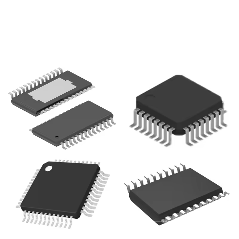 | RTL8367N-VB-CG | Realtek | 2,940 | |
| RTL8367S-CG | Realtek | 7,160 | |
| RTL8363NB-VB-CG | Realtek | 8,500 | |
 | RTL8370MB-CG | Realtek | 4,810 | |
| RTL8380M-VB-CG | Realtek | 3,930 |
It is an architecture worth evaluating for that purpose. Realtek identifies five integrated 10/100/1000M copper PHYs and a nonblocking switching fabric. Suitability still depends on the traffic map, current device-specific implementation guidance and the completed board's test results. Four sources sharing one destination can overload that destination even when every link negotiates at Gigabit speed. Start by allocating all external and internal connections, then budget the busiest egress rather than judging the design only by its socket count.
They cannot sustain their combined full offered rate through one 1 Gbps egress. Temporary buffering can absorb a short mismatch, while flow control may move waiting time upstream, but neither increases the destination link's capacity. For example, four sources at 300 Mbps offer 1,200 Mbps before accounting for the precise traffic measurement convention. Reduce the sustained demand, distribute destinations or change the available egress architecture. Test burst behavior separately because an acceptable average can still conceal synchronized overload.
Do not assume that it can. Preserve the complete RTL8367N-VB-CG ordering string when requesting the schematic guidance, footprint, electrical limits and configuration information. Similar family names do not establish matching pin assignments or software behavior. A public product overview is useful for architecture screening, but board release needs current implementation documentation for the exact device. If a source is preliminary or leaves a value unresolved, record that as an open requirement and obtain authoritative clarification before relying on it.
By Eyki Chen
The RTL8367N-VB-CG from Realtek is a five-port Gigabit Ethernet switch controller with integrated copper PHYs. It is worth evaluating when a product needs five wired network connections in a compact design. The deciding question is where the traffic goes: independent port pairs and four devices sharing one uplink create different workloads. A useful selection starts with that traffic map, then checks configuration access, board support and the exact VB device identity.
A small switch can look straightforward on a block diagram: five connectors, one controller and a power input. Its job becomes less straightforward when those connectors lead to cameras, a storage appliance, a controller and a router. Devices that spend most of their time talking to one destination compete for that destination's link. Devices communicating across separate port pairs can use different paths concurrently. Counting sockets alone misses this distinction.
Realtek's public product page identifies this part as a five-port 10/100/1000M controller with five integrated Gigabit PHYs, a nonblocking switching fabric and internal packet buffering. It lists a QFN88 package, a 25 MHz crystal and optional EEPROM configuration. These details support a compact copper-switch architecture. They do not establish a router CPU connection, a complete enclosure design or application throughput under every traffic pattern. Realtek product overview.
Figure 1. Illustrative five-port fan-in topology. Four sources share one destination link; the drawing shows a workload assumption rather than an internal silicon implementation. Architecture context: Realtek's public RTL8367N-VB-CG product overview. Figure 2. Calculated aggregate rates for four equal-rate sources. The dashed 1 Gbps line is the nominal egress ceiling, not an application-throughput guarantee. Values follow four times the per-source rate in Table 2; no hardware measurements are plotted.No. PHY integration consolidates silicon functions, but the cable-facing implementation still needs the appropriate magnetics, connectors, protection and board layout. Their requirements depend on the intended product and installation environment. Power over Ethernet also needs its own role, power budget and circuitry; an Ethernet switch controller does not by itself establish a complete PoE design. Verify the finished assembly under the relevant product requirements instead of treating a feature list as evidence of enclosure, power or environmental qualification.
RTL8367S-CG adds extension-interface options around five copper PHYs. RTL8363NB-VB-CG is relevant to a smaller two-copper-port architecture. RTL8370MB-CG expands to eight copper PHYs, while RTL8380M-VB-CG adds an embedded-processor management architecture with eight copper links and two SGMII/1000Base-X interfaces. These are four distinct Realtek devices with documented architectural relationships. They are not approved drop-in substitutes. Recheck package, interfaces, configuration software, power design and current orderability for the selected candidate.
Measure loss and latency across the intended source-to-destination patterns, using different frame sizes, synchronized bursts and mixed negotiated link speeds. Retain the offered load, test duration, configuration version and endpoint capabilities so the result can be reproduced. Check power-cycle recovery and link renegotiation as well. A large file transfer can succeed while rare delay spikes or startup faults remain hidden. Acceptance limits should follow the application's timing and data-delivery needs and should be set before evaluating the final results.
Choose this architecture when five copper links meet the connection plan and the busiest destination can accept their combined traffic. If the product also needs a dedicated processor-facing Ethernet interface, draw that connection explicitly before selecting a controller. A processor connected through one of the five copper ports consumes one of those ports. A separate expansion interface, where required, changes the shortlist.
Table 1. Publicly documented architecture and the design decision it supports.
| Public feature | Practical value | Decision still required |
|---|---|---|
| Five integrated 10/100/1000M copper PHYs | Consolidates the switch and physical interfaces | Allocate every external and internal connection |
| Nonblocking switch fabric | Supports concurrent forwarding across available paths | Check destination contention and packet mix |
| Internal packet buffering | Provides temporary storage during forwarding | Establish acceptable burst loss and latency by test |
| QFN88 package | Supports a compact controller footprint | Obtain current land pattern and assembly guidance |
| Optional EEPROM configuration | Offers a configuration-storage route | Confirm supported settings and production programming |
An integrated PHY reduces the number of separate ICs, but cable-side protection, magnetics, connector placement and power delivery still occupy board area. A package outline cannot predict the finished product's dimensions. In a compact enclosure, connector height and cable bend clearance may constrain the layout more strongly than the controller footprint.
The exact ordering string also matters. Keep RTL8367N-VB-CG in the bill of materials, manufacturer correspondence and approved component record. Do not silently shorten it to a similarly named non-VB part when collecting a schematic, footprint or initialization example. Similar family names are a reason to investigate compatibility, not evidence that compatibility has already been established.
Consider a bench instrument with four networked acquisition modules and one workstation. Each module has its own Gigabit link, yet all four send measurement files to the workstation. The workstation-facing port is the common exit. Replacing short cables with better ones will not increase that port's nominal rate above its negotiated link speed.
A different instrument might use two isolated pairs of devices for continuous exchange and reserve the fifth port for occasional service traffic. That arrangement has less common-destination contention even if the sum of traffic across the system is similar. The distinction should appear in the design requirements as a source-to-destination map, with expected sustained rates and bursts for each path.
Specify behavior during unusual but credible events as well. Firmware updates, file recovery and simultaneous startup can create a traffic pattern that differs from normal operation. A product that works while modules stream independently may stall when all modules upload a backlog after a network interruption. That event belongs in the traffic budget before it becomes a field complaint.
A Gigabit link provides a nominal one billion bits per second in one direction. The application receives less useful payload because frames and higher-layer protocols consume part of that capacity. For an early architecture check, comparing aggregate offered traffic with the nominal link rate is still valuable: a workload already above that ceiling cannot be fixed by optimistic assumptions about overhead.
Take four sources feeding one destination. At 200 Mbps each, the aggregate is 800 Mbps. At 300 Mbps each, it is 1,200 Mbps. Four sources at 300 Mbps cannot sustain their full offered rate through one 1 Gbps egress, even with a nonblocking fabric. The shortfall is a topology constraint, not proof of a faulty switch.
Table 2. Illustrative fan-in budgets for four sources and one 1 Gbps destination link.
| Offered rate per source | Aggregate offered rate | Nominal margin to one egress | Engineering interpretation |
|---|---|---|---|
| 100 Mbps | 400 Mbps | 600 Mbps | Comfortable nominal capacity; still test bursts |
| 200 Mbps | 800 Mbps | 200 Mbps | Potential fit after protocol and burst accounting |
| 300 Mbps | 1,200 Mbps | Negative 200 Mbps | Sustained demand exceeds the link ceiling |
| 500 Mbps | 2,000 Mbps | Negative 1,000 Mbps | Requires traffic reduction or architecture change |
These examples use decimal rates and assume every source targets the same destination. They are calculations, not measured performance of a board. The positive margin in the second row is not a guaranteed reserve for user data: the definition of the offered rate must be consistent with the definition of the egress rate. Application counters, Ethernet frame counters and physical wire occupancy can report different numbers for the same transfer.

Buffering can absorb a temporary mismatch between arrival and departure rates. It cannot make a permanently overloaded output keep up indefinitely. If the combined arrival rate is 2 Gbps and the departure rate is 1 Gbps for 100 microseconds, the excess is 100,000 bits, or 12,500 bytes. That is an illustrative storage requirement before considering existing occupancy, implementation details or how packet storage is allocated.
This calculation does not state the device's buffer capacity. Its purpose is to turn an application event into a requirement that can be tested. Record the burst duration and recurrence interval, then check whether the system drains between bursts. Two workloads with the same average throughput can have very different loss behavior when one sends smooth traffic and the other sends synchronized bursts.
Flow control changes the behavior of congestion, but it does not remove the capacity limit. Realtek lists IEEE 802.3x flow control and backpressure. If flow control is enabled and honored, an upstream sender may pause instead of continuing to fill a downstream queue. The application then experiences delayed transmission somewhere else in the system. Whether that is acceptable depends on the source's own buffering and timing requirements.
A camera pipeline, for example, might tolerate a short delay in a file transfer but fail if acquisition cannot pause. A storage application may prefer delay to retransmission. Define the desired behavior for each workload, rather than treating “flow control supported” as a complete answer. Test both the switch and the devices attached to it because end-to-end behavior requires cooperation.

A successful file copy is useful evidence for that particular setup. It is weak evidence for all possible forwarding workloads. Large frames carry more payload per forwarding decision than small frames, while a bursty source places a different demand on buffering than a smoothly paced one. An evaluation should retain the traffic dimensions that matter to the intended product.
RFC 2544 provides established terminology and methods for network-device benchmarking, including throughput, latency, frame loss and back-to-back frames. It is a useful basis for organizing a laboratory test, with results tied to the test conditions. It does not certify a completed product or replace application-specific validation. RFC 2544, Benchmarking Methodology for Network Interconnect Devices.
Start with repeatable, isolated tests so a slow endpoint does not masquerade as a switch limitation. Record generator and receiver capabilities, cable lengths, negotiated speed, duplex state, frame sizes, offered load and duration. If the receiver cannot consume the intended load, increasing the transmitter's rate will mostly measure the receiver's weakness. Establish the endpoint baseline before attributing loss or delay to the controller.
Table 3. A workload-oriented evaluation sequence.
| Test condition | What it reveals | Evidence to retain |
|---|---|---|
| Independent port pairs at controlled load | Concurrent forwarding without common egress contention | Per-port received frames and loss |
| Four inputs aimed at one output | Congestion behavior at a shared destination | Offered load, drops, pauses and recovery |
| Small and large frames | Sensitivity to packet rate and frame occupancy | Frame-size-specific throughput and latency |
| Repeated synchronized bursts | Queue pressure beyond average-rate estimates | Burst length, interval and worst delay |
| Mixed negotiated link speeds | Behavior when one destination is slower | Link state, counters and application response |
A test that reports zero loss without reporting delay can miss a serious problem. A long queue can preserve packets while making their information stale. For a monitoring dashboard, that delay might be acceptable. For an interactive controller, the same delay could violate the response-time requirement. Define a limit for both delivered traffic and delivery age where timing matters.
Use a percentile or a maximum over a stated observation window, and preserve the distribution if possible. An average alone hides infrequent pauses. Repeat the important cases after link renegotiation and after the system returns from a power cycle. An intermittent startup configuration problem can be invisible in a test that begins only after an operator has manually restored connectivity.
Mixed-speed operation deserves its own trial. A single destination negotiating at 100 Mbps can become the bottleneck even when the other ports run at Gigabit speed. The resulting slowdown may be caused by a damaged cable or an attached device's capability, rather than the forwarding fabric. Product diagnostics should expose the negotiated state clearly enough for an installer to distinguish those cases.
The public feature list includes jumbo frames up to 9,216 bytes. Treat that as a capability to qualify along a complete path. A larger frame must be accepted by the relevant endpoints and intervening equipment. Enable it only when the application benefits and the deployment can maintain a consistent configuration; otherwise the support cost may outweigh a modest reduction in overhead.
A useful jumbo-frame test includes a deliberate mismatch. Configure one endpoint or path segment differently and observe whether the application detects the problem cleanly. The objective is not to encourage inconsistent deployment. It is to learn what a technician will see when a replacement device arrives with default settings. Recovery behavior is part of a usable network product.
When a transfer falls short, first repeat it with only one source and one destination active. If the shortfall remains, compare the endpoints directly using a known-good connection and the same application settings. A processor, storage device or operating-system buffer can limit the result before the switch reaches any meaningful forwarding limit. The comparison narrows the problem without requiring an unsupported assumption about the controller's internal queues.
Next add the other sources one at a time while retaining per-port observations. A gradual slowdown as total offered traffic approaches the shared link's capacity suggests a different problem from an abrupt failure when one particular device connects. Preserve the order of those changes. The sequence often explains more than a single screenshot of aggregate throughput.
Test the reverse direction separately. A device may receive quickly but transmit slowly, or its application may perform different work in each direction. Then run simultaneous traffic in both directions if the intended workload requires it. Full-duplex link operation makes both directions available, but it does not prove that endpoint software can sustain both at the same time.
Keep the measurement interval consistent when comparing counters. One counter sampled before a burst and another sampled after it can create an apparent discrepancy even when neither is wrong. Note whether a figure counts delivered application bytes, Ethernet frames or a generator's offered load. Do not subtract numbers with different boundaries and label the difference as switch loss.
If a repeatable fault follows one cable or connector, investigate that path before changing the software configuration. If it follows a traffic pattern across different ports, investigate contention and endpoint behavior. If it appears only after a power interruption, return to startup and configuration verification. These observations do not identify every root cause, but they make the next experiment specific enough to be useful.
Finally, retain a minimal reproducer: the smallest set of devices, settings and traffic streams that still produces the failure. Include a passing comparison under one clearly stated change. That package gives manufacturer support a concrete problem to investigate and prevents a future board revision from being judged against an unrepeatable anecdote. A design team can also rerun it after an approved component or firmware change to check that the original problem has not returned.
The switch controller's feature list is only one input to board design. A working product also depends on power integrity, clocking, reset behavior, cable interfaces and configuration storage. These are connected decisions: a brownout that resets the controller while another device keeps transmitting can produce symptoms that resemble congestion or faulty software.
Before schematic release, obtain current documentation for the exact VB ordering code through the manufacturer or its authorized support channel. The public overview establishes the architecture; it is not a complete electrical design package. Use current device-specific electrical and layout guidance for implementation, especially where a document is preliminary or leaves a parameter unresolved. A missing limit should remain an open engineering requirement until an authoritative source resolves it.
Optional EEPROM configuration can help a product start in a known state, but it introduces a production artifact that must be controlled. Define who creates the image, how its version relates to the hardware revision and how programming is verified. A correct controller assembled with an incorrect configuration can be harder to diagnose than a visibly wrong component.
Include a recovery route for a blank or corrupt configuration device. The appropriate method depends on the supported hardware and software interface, so it should come from current manufacturer guidance. The product requirement is simpler: a manufacturing technician needs a documented way to identify the loaded configuration and restore the approved one without guessing register values from another family member.
Power-cycle testing should cover realistic supply ramps and interrupted power, with the expected startup behavior recorded. Verify that every intended port returns to service and that the management or configuration path remains accessible. A test that checks only one successful cold start provides little confidence about an installation that will experience repeated outages.
Clock selection deserves the same discipline. The public page's 25 MHz crystal requirement is a reference-clock detail, not a promise that an arbitrary crystal and load network will work. Frequency tolerance, loading and placement must follow the current design guidance. Do not infer high-speed interface timing from the crystal frequency alone.
Five integrated PHYs do not remove the cable-facing portion of the design. Magnetics, connector arrangement, protective components and grounding choices must suit the intended environment. A quiet office enclosure and a cable-connected machine cabinet can expose a board to different interference and installation conditions. Verify the finished assembly under the applicable product requirements rather than assuming an integrated PHY resolves them.
Power over Ethernet is another separate decision. A switch with Ethernet connectors is not automatically a power-sourcing device, and an attached product does not automatically become a powered device. If the application requires PoE, specify the role, power budget and additional implementation independently. This prevents a network architecture drawing from quietly becoming an unsupported power-system claim.
Likewise, a Layer 2 forwarding function does not establish routing, firewalling, secure remote management or application isolation. Define those responsibilities at the system level. If a management processor is required, its connection, boot sequence, update process and failure behavior belong in the architecture alongside the switch, not in a late software appendix.
The closest useful comparison depends on what is missing from the five-port design. Additional host interfaces, fewer copper ports, more copper ports and an embedded management processor are different requirements. The four models below represent those choices. Their complete names appear on Realtek's public product pages; they are distinct base devices rather than alternate packing options.
Table 4. Four related Realtek switch controllers and their architectural differences.
| Exact model | Publicly documented port arrangement | Important distinction | When to investigate |
|---|---|---|---|
| RTL8367S-CG | Five integrated copper PHYs plus two extension interfaces | LQFP128; SGMII/HSGMII and MII/RGMII routes | Five copper ports also need processor-facing connectivity |
| RTL8363NB-VB-CG | Two integrated copper PHYs plus one extension interface | QFN76; lower copper-port count | A compact embedded product needs fewer external links |
| RTL8370MB-CG | Eight integrated copper PHYs plus two extension interfaces | TQFP176 with exposed pad; larger port architecture | Expansion beyond five copper connections is required |
| RTL8380M-VB-CG | Eight copper PHYs and two SGMII/1000Base-X interfaces | Embedded MIPS processor for a managed-switch architecture | Management processing changes the system requirements |
Sources: Realtek's RTL8367S-CG, RTL8363NB-VB-CG, RTL8370MB-CG and RTL8380M-VB-CG product pages. This comparison establishes architectural relationships, not pin compatibility, firmware compatibility or present inventory.
The RTL8367S-CG is the most direct candidate to investigate when five copper connections remain necessary but a processor connection is missing. Its extension interfaces address a different connection plan. That benefit comes with a different package and implementation requirements. Decide whether the processor needs a parallel or serial interface before treating the extra ports as interchangeable resources.
The smaller RTL8363NB-VB-CG moves in the opposite direction. It is relevant when an embedded device needs two cable connections and an internal interface, rather than a five-socket desktop switch. Choosing fewer ports can make the architecture clearer, but only if the reduced connectivity matches the product's future service and expansion needs.
The eight-PHY RTL8370MB-CG is a scaling option. More local ports can reduce the need for an external switch, yet they also increase connector count, layout work and the number of traffic patterns to validate. If those additional ports still share one busy destination, the original egress bottleneck remains. Port expansion and uplink expansion should therefore be evaluated separately.
The RTL8380M-VB-CG belongs on the list when management processing is part of the requirement. Its integrated processor changes the software and memory architecture as well as the port arrangement. That makes it a broader system alternative, not a substitute to place on an existing five-port footprint. Compare the development resources and support path as carefully as the forwarding features.
For any candidate, ask the supplier to confirm the full ordering code and current documentation package before committing the design. A public product page can establish identity and broad capability without establishing stock, lead time or suitability for a particular board. Keep those procurement and engineering checks distinct so neither is mistaken for the other.
A useful evaluation ends with evidence that another engineer can reproduce. Preserve the traffic map, configuration version, hardware revision and test setup with the results. If a failure disappears after changing both firmware and a cable, the record should not imply that the root cause is known. Change one variable at a time when practical, and mark unresolved interactions clearly.
Table 5. Release questions for a five-port switch design.
| Release question | Minimum useful evidence | Action if unresolved |
|---|---|---|
| Does every required connection fit? | Approved port map including internal links | Revise topology or controller shortlist |
| Can the busiest destination keep up? | Sustained and burst traffic budgets plus measured results | Reduce demand or increase available egress capacity |
| Is startup repeatable? | Power-cycle and configuration-verification records | Resolve sequencing or programming behavior |
| Does the board match the exact device? | Current VB-specific schematic and layout review inputs | Obtain authoritative implementation guidance |
| Can a field fault be diagnosed? | Link-state, loss and recovery observations | Add diagnostics and a recovery procedure |
Set acceptance limits before looking at the final results. Otherwise an inconvenient delay spike or rare drop can be rationalized after the fact. Limits can differ between a service port and a continuous acquisition path, provided the distinction follows the product's actual needs. The goal is a defensible release decision, not a single impressive throughput number.
Also repeat the critical workload with the intended enclosure, supply and cable arrangement. An open bench board can hide thermal and interference interactions introduced by the final assembly. Record ambient conditions and operating duration so a pass remains meaningful when someone reviews it months later. If environmental qualification has not been completed, do not describe a traffic test as evidence that it has.
For procurement, carry the exact model into the approved source record and keep substitutions subject to engineering review. A similar name or a larger feature list does not establish that an alternate can use the same footprint, configuration image or production test. The cost of a substitution includes the work needed to restore that evidence.
The RTL8367N-VB-CG is a reasonable architecture to evaluate for a compact five-copper-port switch when the traffic map fits its links. The decisive check is the busiest egress under the real workload, followed by current VB-specific implementation support. Establish those two points early, and the remaining work becomes a clear sequence of board integration, repeatable testing and controlled production configuration.